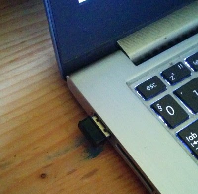
Thursday, January 7, 2016

Data transfer to Android device over infared link

The three previous parts (here, here and here) of this series introduced the infrared-to-Android gateway. Even though those prototypes captured the signals of an ordinary IR remote, I already hinted that I was aiming for something more exciting. In this part, we will replace the IR remote with our own IR transmitter. Once we have our own IR transmitter, we will be able to transfer our own data over IR light. This data link is not reliable enough to transfer large amount of data but in lot of the cases that's not required. E.g. to transfer the data of a temperature/humidity sensor, 32 bit is more than enough.

So what can we expect from IR-based data transfer with respect to more popular, radio-based transfer? There are advantages and disadvantages.

  • Advantage for the IR solution is that it is extremely cheap and also extremely power-efficient.
  • Advantage for radio is that IR-based solution always requires line of sight, while radio waves can - to some extent - traverse walls, etc.
  • Advantage for radio is that the IR transmitter has to be aimed at the receiver, if for some reason the receiver and the transmitter move with respect to each other, they lose contact very easily.
There's also the question of range. Ordinary TV remotes work up to 3-4 meters of distances which is nice for an inexpensive consumer device but is not enough even for indoor sensor network use cases. In this part I try to figure out what the distance limit may be.

For starter, this question is not defined precisely. With sophisticated optics, high-powered transmitters and careful targeting, IR data transfer can be accomplished over significant distances. But we said that we are looking for cheap hardware so we can't rely on sophisticated devices. We need some sort of optics but this should be simple and cheap. That's why I went to a second-hand toy shop and bingo, I found the IR transmitter of Thinkway Toys' Lazer Stunt Chaser. The small toy car has long been lost, but the handgun-like IR transmitter somehow made its way to Hungary. This cheap, plastic toy is a marvelous device. It promises 12 meters of effective range and even though the mounting of the IR light source and the plastic optics is made of cheap materials, it is surprisingly efficient. It even has a normal (red) LED emitting its light through the transparent housing of the infrared LED which produces visible red light circle of about 10 cm of diameter facilitating the targeting of the IR transmitter.

So how far can it transmit our IR codes? In order to try it out, I took apart Thinkway's IR transmitter and replaced the circuitry driving the IR LED with mine. The new emitter circuit is based on an Arduino Pro Mini 3.3V/8MHz and the schematics looks like this:


The software works on any Atmel ATmega328p-based boards, e.g. on Arduino Uno. If your MCU uses power source with higher voltage than 3.3V, adapt R2 accordingly. E.g. for an 5V Arduino Uno board, you need about 160 Ohm.

So this is how I hacked my circuit into the IR transmitter.


Note the two LEDs: the IR led in the tube-like mounting and the ordinary red LED behind it that is used for targeting. Also, note how the IR LED is connected to the ATmega328p's PD3 pin - IRLib which is the software used to construct the transmitter selects OC2B PWM output so the primary Timer2 PWM pin (PB3) would not work.

Click here to download the source code of the IR transmitter.

Open sketch/Makefile and update the ARDUINO_DIR according to your installation. Also, update ISP_PROG according to the programming tool you use to deploy the code. I used USBtinyISP, the Makefile is set accordingly. If your board has USB programming port (like the Arduino Uno has), then setting ISP_PROG is unnecessary.

In order to deploy the code into the ATmega328p, say:

make ispload

if you use a programming tool or simply

make upload

if you don't need a tool.

About the code. The application emits a 32-bit NEC IR code every 4 seconds. The value of the code is increasing. The application is based on the same IRLib library as the receiver was, this time the only modification necessary was that I disabled all the receiver routines as this device does not receive any data. And that's my response to all the people worrying about the security of the Internet of Things: if the Thing is physically unable to receive any data then it cannot be hacked, period.

Even though this application is not particularly energy-efficient, care was taken to implement the sleeping part with the lowest possible energy consumption. Hence the delay logic does not use the Arduino delay() function but puts the MCU into deep sleep and triggers the watchdog timer to launch a new iteration. Read Nick Gammon's excellent analysis of ATmega328p power saving techniques for further explanation.

So what are my experiences? Using the infrared-to-Android gateway I presented previously which is based on a basic IR receiver circuit (TSOP1738) without any optics and the IR transmitter hacked into a Thinkway toy, which uses cheap plastic optics, I was able to transmit codes to a distance of about 10 meters (and then receive the code on the Android device over BLE). Of course, not every transmission was successful. My experience is that the code needs to be repeated about 5 times if you want to be nearly 100% sure that it arrives (100% can never be achieved). One important take-away is that the targeting LED in the Thinkway toy was not there by chance, in order to target the IR receiver, you really need that aid of visible red light circle. But that's about it: 2 LEDs, a cheap MCU and some optics and you can connect sensors from an entire room to one relatively expensive BLE unit. Also, these IR-connected sensors need very little energy. So it is worth considering the advantages/disadvantages.

Wednesday, December 30, 2015

Infrared-to-Android gateway implementation with interrupts

In the previous parts of this series the infrared-to-Android gateway based on the RFDuino hardware and an improved version of the hardware were presented. The improved hardware offered quite reliable IR code recognition even when the BLE connection was in operation. Trouble with that implementation was the polling nature of the code; even though the IR reader support hardware is capable of raising an interrupt when a new time measurement is available, the code did not handle that interrupt, instead it polled the interrupt signal.

Click here for the updated gateway code. Click here for the (unchanged) Android application serving the gateway.

The reason I did not implement proper interrupt handling was the I2C library (called "Wire") coming with the RFDuino. Even though the nRF51822 (on which the RFDuino is based) is able to handle its I2C interface (called TWI, two-wire interface) by means of interrupts, it was not implemented in the "Wire" library. When the MCP23008 GPIO port extender raised an interrupt, the MCU was expected to read the MCP23008's capture register by means of an I2C transaction. As the "Wire" library was polling-based, this transaction held back the GPIO-handling interrupt for too long time, freezing the system.

The solution was transforming the "Wire" library into interrupt-based implementation. Now as my goal was a limited functionality (reading one register of an I2C periphery) I did not do it properly. I moved the entire "Wire" library into the application project (see it under the "lib" directory), renamed it to "Wire2" and introduced a couple of new methods, more importantly sendReceiveInt (in lib/Wire2.cpp). This method initiates the write transaction of a data array followed by a read transaction of another data array over I2C, all handled by TWI interrupts. This means that sendReceiveInt returns immediately and the actual data transfer happens in the background. This new method is invoked in the GPIO interrupt handler (GPIOTE_Interrupt in sketch/irblegw3.ino) but this time the GPIO interrupt handler completes very quickly as its job is only to initiate the TWI transaction handler. When the TWI transaction is finished, the TWI interrupt handler invokes the onReceive callback that ends in the application code (twi_complete in sketch/irblegw3.ino).

The most important outcome of this - quite significant - change is that the MCU does not spend its time spinning on the GPIO port reading loop. Instead, it waits for interrupts in ultra-low power mode (sketch/irblegw3.ino, IRrecvRFDuinoPCI::GetResults method, RFduino_ULPDelay invocation) which is important if the infrared-to-Android gateway is powered by a battery. As you may have guessed, my goal is not to fiddle with IR remote controllers, I intend to build a short-range network comprising of infrared, BLE and cellular links and the infrared-to-BLE gateway was just one step.

Wednesday, December 16, 2015

Improved hardware for the infrared-to-Android gateway

In the previous post I presented the results of my experiments with the nRF51822-based RFDuino as infrared-to-Bluetooth Low Energy gateway, accompanied by an Android client app. The outcome of that experiment was that the nRF51822 BLE soft stack and the purely software-based IR receiver is not a good match as the BLE soft stack "steals" enough cycles from the Cortex M0 CPU so that the IR reading becomes very unreliable no matter which implementation alternative we go for (3 different alternatives were attempted). I promised an improved hardware that overcomes this limitation and this post is about this improved hardware.

The essence of our problems with the BLE soft stack was that in case of very tight timings that the IR receiver requires, the main CPU is not suitable anymore for measuring time periods. Typical IR timing is in the 500 microsec-2 millisec range, this is the time period we should be able to measure reliably. With the BLE soft stack in operation, delays are introduced into the time measurement code by the background interrupt routine serving the soft stack and time measurement of this precision will be wildly off. I considered two options.

  • The most evident option is to drop the integrated MCU-BLE radio combo that the nRF51822 is and go for a separate MCU-BLE modem option. For example an Arduino Pro Mini with a BLE121LR modem would have been a perfect fit as there are both of these modules in my drawer. While this hardware would have been definitely more hassle-free than the nRF51822, setting it up would have required two different programming tools (I have both but that's not necessarily true for the general blog reader out there) and I am still uneasy about soldering the BLE121LR - those pads are smaller than my capabilities.
  • Extending the RFDuino with a dedicated hardware for time period measurement sounded more attractive for me as this was less evident. The functionality we expect is that the MCU is not doing any time measurement. The external hardware must be capable of measuring the time periods between the edges of the TSOP1738 output signal and deliver these measurements to the MCU. The measuring range is about 500 microsec-2 msec. Larger time periods are still measured by the MCU but in this case the disturbances caused by the soft stack are not that relevant.
Further complication is that while the nRF51822 has 31 general-purpose pins, RFDuino makes only 7 of those available and 2 of them are reserved for USB communication. This requires that the circuit is interfaced with the RFDuino with the lowest number of wires and I2C is the best option (2 wires). nRF51822 has I2C option (called TWI, two-wire interface) so this would work. I was not able to find a single-chip solution that measures and captures time periods in this time range with I2C interface but the circuit is not that complicated.


A 74HC4060 is set up as oscillator and counter. The frequency of the oscillator is about 350 kHz, yielding about 43 microsec time resolution for one counter step, making it convenient to measure between 43 microsec and 5.5 sec with 7-bit resolution. An MCP23008 GPIO-extender with I2C interface provides the conversion to I2C two-wire connection and also has a capture logic. This means that whenever the output level of the IR receiver changes, the MCP23008 stores the current value of the counter in its capture register and raises an interrupt. This way the MCU is not doing any time measurements and the time measurement hardware is able to survive about 1 msec autonomously without service from the MCU.

Click here to download the schematic in Eagle SCH format.

Click here to download the updated RFDuino gateway sources.


As with the previous version, edit the Makefile in the irblegw2/sketch directory and update the RFDUINO_BASE_DIR and the AVRDUDE_COM_OPTS variables according to the layout of the file system and the USB port mapping of the RFDuino USB shield. Then you can simply say "make upload" and the gateway is installed into the RFDuino. The Android client code and its usage is unchanged, check it out in the previous post.

The gateway code represents a step in the right direction. The I2C support library ("Wire") coming with the RFDuino gets stuck when invoked from interrupt handler so this time the MCP23008 interrupt signal is handled by means of polling. The result is that when BLE is active, occasionally there are still lost IR codes even though the quality of the recognition has improved considerably.  I intend to turn the I2C access interrupt-driven but that requires going deep into the nRF51822 that I was not yet able to accomplish in this iteration.

Friday, December 4, 2015

Controlling Android device with an infrared remote

I came across several posts about microcontrollers decoding signals of infrared remote controllers and started to think, how an IR remote can be integrated with an Android smartphone. This post is about a simple use case when I control the media volume of the Android phone with an IR remote.

Long time ago, in a distant galaxy, IR transmitter-receiver was a standard feature of almost any mobile phone. Technological progress has eliminated that feature so we are now forced to build some hardware. We need infrared sensor for sure to capture the remote's infrared signal. But how can we connect that to the phone? Last year's experiments prompted me to choose Bluetooth Low Energy (BLE). Also, the microcontroller platform was determined by my experiences with RFDuino and I happened to have an RFDuino set in my drawer.

The idea is the following. An infrared receiver is connected to the microcontroller that captures and interprets the infrared signals. If the phone is connected to the BLE radio, then the key codes sent by the IR remote are then sent to the phone over BLE. The phone does whatever it wants with the key codes, in my example the volume up, down and mute buttons are handled and are used to influence the volume of the music played by the media player.

The infrared implementation is based on the excellent IRLib code. IRLib assumes that the IR receiver is connected to one pin of the microcontroller so I built the circuit below. A TSOP1738 IR receiver is directly connected to a GPIO pin of the RFDuino which is expected to do all the decoding. SV1 header is only for monitoring debug messages, it is not crucial for the operation of the gateway. If you intend to use it, connect an RS232C level converter similar to this one.


Then came the complications. "Arduino code" is used with great liberty on the internet, as if Arduino meant a single platform. But in reality, Arduino is a very thin layer on top of the underlying microcontroller. Most of the code, tools and articles out there are based on Atmel's extremely popular AVR family of MCUs. These are 8-bit CPUs, equipped with a host of peripherials. The challenger in this domain is not Intel but ARM's Cortex family. RFDuino is a Nordic Semiconductor's nRF51822 System-on-Chip (SoC) which is a Cortex-M0 core with integrated 2.4 GHz radio. BLE is supported by means of a software stack. ARM Cortex is not supported as well as AVRs by the Arduino community and this miniproject is a cautionary tale about this fact.

Click here to download the RFDuino project. In order to compile it, you need to install the Arduino IDE with the RFDuino support as described here.

For starter, the Arduino Makefile I used with such a great success previously does not support Cortex-based systems, only AVRs. A short explanation: I don't like IDEs, particularly not in a project where I would like to see exactly what goes into the compile/link process. Arduino IDE is nice for beginners but is a very limiting environment for more ambitious projects. After several days of heavy modifications, I adapted this makefile to the ARM Cortex tool chain of the RFDuino. Go into the irblegw/sketch directory, open the Makefile and look for the following line:

RFDUINO_BASE_DIR = /home/paller/.arduino15/packages/RFduino

Adapt this according to the layout of your file system. Then type "make" and the entire code should compile. "make upload" uploads the compiled code into the RFDuino, provided that the port (AVRDUDE_COM_OPTS =  /dev/ttyUSB0 in the Makefile) is also correct.

Then came further complications. The IRLib code is also AVR-specific. The differences between Cortex-M0 and AVR are mainly related to interrupt handling, on-chip counters and GPIO options. Polluting the original code with ARM-specific fragments seemed too confusing so I rather disabled the AVR-specific parts if the code is compiled on ARM architecture and implemented the ARM-specific functionality in Cortex-specific subclasses (in sketch/irblegw.ino). There are three implementations (like in the base library) IRrecvRFDuino (which uses 50 microsec periodic interrupt to sample the IR receiver input), IRrecvRFDuinoLoop (which is purely polling-based with no interrupt support) and IRrecvRFDuinoPCI (which sets up an interrupt to detect when GPIO02 changes state). This line determines, which one is used:

IRrecvRFDuinoPCI My_Receiver(RECV_PIN);

And now the biggest surprise. If BLE is not active, all the three implementations work. But if BLE is active, the software stack running behind the scenes on the RFDuino steals enough cycles so that IR reading becomes completely unreliable. The best result is provided by IRrecvRFDuinoPCI (which is activated in the download version) but even that version, after a significant loosening of the matching rules drops about 1 IR key out of 4. Well, folks, that's what I could achieve with this hardware and that's the second important take-away: SoCs with integrated communication stacks (this time BLE, but can be WiFi, GSM, whatever) are notoriously tricky if the sensor processing logic is time-critical.

Click here to download the Android code. To decrease download size, I packed only the files under the app/src/main directory of the Android Studio project.

The Android implementation is quite self-explanatory and is heavily related to this earlier RFDuino example program. This time I wanted to make sure that once the gateway is connected through BLE, the application can be sent to the background so I implemented the BLE connection logic in a service that significantly complicated the code. But after all this wizardry with Android services, the important part is here in IRGWService.java:

if( v == IR_KEY_VOLUME_PLUS ) {
     audioManager.adjustStreamVolume(  
                AudioManager.STREAM_MUSIC,
                AudioManager.ADJUST_RAISE,
                AudioManager.FLAG_SHOW_UI);

...

This is the fragment that maps IR remote keys to actions on the phone. The RFDuino-based gateway does not do any key mapping so it is the Android application that needs to know the meaning of the IR key codes. The following comes from the Philips remote I grabbed for these experiments.


    private static final long IR_KEY_VOLUME_PLUS = 0x20df12edL;

It is highly likely that you will have to change this value according to your remote's key code map. Just press the desired button and check the code.


This project was not a complete success as IR reading is not as reliable as it should be. But it is indeed fun to control the Android phone with an ordinary IR remote. I plan to improve the hardware a bit to make key recognition better so stay tuned (if you care about IR remotes).

Update: check out the follow-up blog posts (this and this).

Wednesday, April 22, 2015

Infrared imaging with Android devices


One of the most evident sensors of Android devices is the camera. An ordinary smartphone's camera is able to capture a lot of interesting information but has its limitations too. Most evidently, its viewing angle depends on the position of the device (so it is not fixed and hard to measure) and its bandwidth is (mostly) restricted to the visible light. It is therefore an exciting idea to connect special cameras to Android devices.


In this post, I will present an integration of FLIR Lepton Long-wavelength Infrared Camera to an Android application over Bluetooth Low Energy connection. Long-wavelength IR (LWIR) cameras are not new. Previously, however, they were priced in the thousands of dollars range (if not higher). Lepton is still pricey (currently about 300 USD) but its price is low enough so that mere mortals can play with it. FLIR sells a smartphone integration product (called FLIR One) but it is currently only available for iPhone and locks the camera to one device. Our prototype allows any device with BLE connection to access this very special camera.

The prototype system presented here needs a relatively long list of external hardware components and it is also not trivial to prepare these components. This list is the following:


  • An Android phone with Bluetooth 4.0 capability. I used Nexus 5 for these experiments.
  • An FLIR Lepton module. My recommendation is the FLIR Dev Kit from Sparkfun that has the camera module mounted on a breakout panel that is much easier to handle than the original FLIR socket.
  • A BeagleBone Black card with an SD Card >4GB.
  • A BLED112 BLE dongle from Silicon Labs (formerly Bluegiga).
The software for the prototype can be downloaded in two packages.

  • This package contains the stuff for the embedded computer.
  • This package is the Android application that connects to it.
Once you got all these, prepare the ingredients.

1. Hook up the FLIR camera with the BeagleBone Black

Fortunately the BBB's SPI interface is completely compatible with the Lepton's so the "hardware" just needs a couple of wires. Do the following connections (P9 refers to the BBB's P9 extension port).


FLIR BBB
CS P9/28 (SPI1_CS0)
MOSI P9/30 (SPI1_D1)
MISO P9/29 (SPI1_D0)
CLK P9/31 (SPI1_SCLK)
GND P9/1 (GND)
VIN P9/4 (DC, 3.3V)


2. Prepare the BBB environment

I use Snappy Ubuntu. Grab the SD card and download the image as documented here. Before flashing the SD card, we have to update the device tree in the image so that the SPI port is correctly enabled. Unpack bt_ircamera.zip that you have just downloaded and go to the dt subdirectory. There you find a device tree file that I used for this project. Beside the SPI1 port, it also enables some serial ports. These are not necessary for this project but may come handy.

Compile the device tree:

dtc -O dtb -o am335x-boneblack.dtb am335x-boneblack.dts

The output is the binary device tree (am335x-boneblack.dtb) that needs to be put into the kernel image file. Let's suppose that the downloaded image file is ubuntu-15.04-snappy-armhf-bbb.img and you have an empty directory at /mnt/img. Then do the following:

fdisk -l ubuntu-15.04-snappy-armhf-bbb.img

Look for the first partition and note the partition image name and the offset:

ubuntu-15.04-snappy-armhf-bbb.img1   *        8192      139263       65536    c  W95 FAT32 (LBA)
...

Note that the actual partition image name may differ depending on the Snappy image you downloaded. Calculate the offset as 8192*512=4194304
Now mount the partition:

mount -o loop,offset=4194304 ubuntu-15.04-snappy-armhf-bbb.img /mnt/img

Then copy the dtb into the image, unmount and write the image to SD card (on my computer the SD card interface is /dev/sdc, check before you issue the dd command!):

cp am335x-boneblack.dtb /mnt/img/a/dtbs
umount /mnt/img
dd if=ubuntu-15.04-snappy-armhf-bbb.img of=/dev/sdc bs=32M

Now you have an SD card that you can insert into the BBB and boot from it. Once you reached the Ubuntu prompt and logged in (ubuntu/ubuntu), there's one thing more: the Snappy prototype application depends on the libpng package which is not part of the default Snappy image. But before you do it, check whether the SPI device was enabled correctly:
root@localhost:~# ls /dev/spidev1.0                                            
/dev/spidev1.0

Now about the png library. Download the armhf image from this location:

wget http://ports.ubuntu.com/pool/main/libp/libpng/libpng12-0_1.2.50-1ubuntu2_armhf.deb


Copy it to the BBB (update your card's IP address according to your network policies):
scp libpng12-0_1.2.50-1ubuntu2_armhf.deb ubuntu@192.168.1.115:~

Then go to the BBB console and install the deb package:
sudo mount -o remount,rw /
sudo dpkg -i libpng12-0_1.2.50-1ubuntu2_armhf.deb
sudo mount -o remount,ro /

3. Prepare the BLE dongle

The BLED112 stores the GATT tree in its firmware, hence in order to provide the GATT services that connect the BBB with the Android device, a new firmware needs to be generated and installed in the dongle. The config files are located in the config subdirectory in the bt_ircamera.zip archive. Follow the steps in this post to generate and install the new firmware. Once you are done, you can simply plug the dongle into the USB port of the BBB.

4. Install the prototype applications

The prototype system has two parts. The application running on the BBB acts as BLE server, fetches images from the FLIR camera and transmits them over BLE. The Android application acts as BLE client, fetches images from the BLE server and displays them. The BBB part is located in bt_ircamera.zip and the Android part is in IRCamera.zip. The latter is just the source part of the Android Studio project tree - I omitted all the garbage that Android Studio generates into the project folders. For the BBB installation, follow the instructions in this blog post. Launch the BBB application like this as root:
/apps/ircamera.sideload/1.0.0/bin/ircamera /dev/ttyACM0
and you are ready to go. On the Android side, select the BLE node with the name "test", connect, click the "Take picture" button, wait for the image to download and there you are. Note that the images are saved on the SD card, which means that they also appear in the stock "Photos" application.

Now at last we can get to the technical issues with this prototype. One interesting aspect is that there is no standard BLE service that provides the functionalities - image capture triggering, image fetching - our system needs. That's not a problem, we defined our own BLE service. It is easiest to follow this service in irc_gattBLED112.xml (bt_ircamera.zip, config subdirectory).

The service has a custom UUID, generated randomly:

<service uuid="274b15a3-b9cd-4e5e-94c4-1248b42b82f8" advertise="true">

Also, its 3 GATT characteristics are in the non-standard UUID domain:

<characteristic uuid="00000000-b9cd-4e5e-94c4-1248b42b82f8" id="irc_len">
...
<characteristic uuid="00000001-b9cd-4e5e-94c4-1248b42b82f8" id="irc_offs">
...
<characteristic uuid="00000002-b9cd-4e5e-94c4-1248b42b82f8" id="irc_pic">

The interaction goes like the following. The BLE client connects and reads the irc_len characteristic. This characteristic is tagged as "user" on the BLE server side meaning that the BLE application must generate the value on the fly, when the attribute is read. In our case, reading this attribute fetches an image from the FLIR camera, converts it into PNG format and stores it in the apps' data folder, returning only the PNG file size. The Android application now can fetch the image piece by piece. First the Android application writes the irc_offs characteristic to inform the BLE server, what is the starting location of the fragment it wants to fetch. Then it reads the irc_pic characteristic which returns a maximum of 20 bytes of image data. This makes the image download very slow (takes about 10-20 second to download a general 5-6 Kbyte image to the Android application) but the restriction comes from a BLE protocol layer. Maybe the old RFCOMM from Bluetooth Classic would have been actually a better option for this application.

Update: I updated the client/server application to make the download faster (it is still quite slow). In order to speed up, I removed the explicit setting of the file offset (so the irc_offs characteristic is not used anymore). This made the download faster but there's still room for improvement.

Other than the issue with fragment size, both applications are pretty straighforward. Maybe the colors of the IR image are worth discussing a bit. The FLIR camera returns a matrix of 80x60 pixels, each pixel has a depth of 12 bit. Grayscale presentation is the most evident option but most displays have only 256 gray colors. In order to make the IR shades more visible, I used fake coloring. The algorithm is very simple: after the image is fetched, the maximum and the minimum IR intensity is calculated and the range between the two are mapped into a rainbow gradient of 400 colors.

Friday, February 6, 2015

BLED112 on BeagleBone

In the previous post I demonstrated, how a Bluetooth Low Energy dongle can be used to connect a PC and an Android device. While this is sort of project is appealing, connecting PCs and smartphones is not such an interesting use case. It is much more interesting, however, to transfer the PC-side program directly to an embedded device and that's what I will demonstrate in this post.

The Android application used in this post did not change, you can download it here. The BLE server application was updated according to the embedded platform's requirement, you can download the new version here.

There are two baskets of embedded platforms out there. One of them is optimized for low power consumption. They are too limited to run a full-scale operating system therefore their system is often proprietary. Arduino (of which we have seen the RFDuino variant) is one of them but there are many more, e.g. Bluegiga modules also have a proprietary application model. We can typically expect power consumption in the 1-10 mA range with some platforms offering even lower standby consumption.

The other basket contains scaled-down computers and they are able to run stripped down versions of a real operating system. Their power consumption is in the 100-500 mA range and they often sport 100s of megabytes of RAM and gigabytes of flash memory. They are of course not comparable to low power platforms when it comes to power consumption but their much higher performance (which can be relevant for computation-intensive tasks) and compatibility with mainstream operating systems make them very attractive for certain tasks. The card I chose is BeagleBoard Black and my main motivation was that Ubuntu chose this card as a reference platform for its Ubuntu Core variant.

The point I try to make in this post is how easy it is to port an application developed for desktop PC to these embedded computers. Therefore let's just port the BLE server part of the CTS example demo to BeagleBone Black.

There are a handful of operating systems available for this card. I chose Snappy Ubuntu - well, because my own desktop is Ubuntu. Grab an SD card and prepare a Snappy Ubuntu boot media according to this description. It worked for me out of the box. You can also start with this video - it is really that easy. Once you hooked up the card with your PC, let's prepare the development environment.

First fetch the ARM cross-compiler with this command (assuming you are on Ubuntu or Debian):

sudo apt-get install gcc-arm-linux-gnueabihf

Then install snappy developer tools according to this guide.

Then unpack the BLE server application into a directory and set up these environment variables.

export CROSS_COMPILE=arm-linux-gnueabihf-; export ARCH=arm

Enter the beagle_conn_example directory that you unpacked from the ZIP package and execute:

make

This should re-generate cts_1.0.0_all.snap which is already present in the ZIP archive in case you run into problems with building the app. The snap is the new package format for snappy. Then you can install this package on the card.

snappy-remote --url=ssh://192.168.1.123 install ./cts_1.0.0_all.snap

You have to update the IP address according to what your card obtained on your network. The upload tool will prompt you for username/password, it is ubuntu/ubuntu by default.

Update the GATT tree in the BLED112 firmware as described in the previous post. Plug the BLED112 dongle into the BeagleBoard's USB port. Then open a command prompt on the BeagleBoard either using the serial debug interface or by connecting to the instance with ssh and execute the following command:

sudo /apps/cts.sideload/1.0.0/bin/cts /dev/ttyACM0

The familiar console messages appear and you can connect with the Android app as depicted in the image below.


One thing you can notice here is that Snappy's shiny new package system is not ready yet. In order for this package to access the /dev/ttyACM0 device (to which the BLED112 is mapped without problem), it has to run as root. This is something that the Snappy team is yet to figure out. The experience, however, is smooth enough that application development can be started now.


Tuesday, December 30, 2014

Integrating an Android smartphone application with the BLED112 module

My conclusion with the RFDuino adventures was that RFDuino is a perfect platform to start familiarizing with the Bluetooth Low Energy (BLE) technology. BLE programming was made so simple with RFDuino that it provides quick success. Simplification comes with limitations, however, and eventually time has come for me to step further toward a more flexible BLE platform. Bluegiga's BLE121LR long range module seems to have outstanding range but first I tried a piece of hardware that is equivalent from the API point of view with the BLE121LR but is easier to start with and that is Bluegiga's BLED112 USB dongle.


The BLED112 implements the same API (called BGAPI, check out Bluetooth Smart Software API reference) that other Bluegiga BLE modules do but there's no need to buy the pricey DKBLE development board or build any hardware. It plugs neatly into the USB port and is functional without any additional piece of hardware. From the serious BLE application development perspective it has drawbacks too. Firstly, its USB interface is drawing a constant 5mA current so this solution is not very much "low energy". Second disadvantage is that its single USB interface is shared between the BGAPI API and the programming interface so installing scripts into the BLED112 is a risky enterprise. If the script running on the BLED112 occupies the USB port, there's no way to update it so the module is essentially bricked. Hence in this exercise we will keep the BLE application logic on the PC hosting the module and talk to the module with BGAPI. This is very similar setup when the application logic is running on a microcontroller or embedded PC.

Click here to download the Android client and the PC server example programs.

In this exercise, we will implement the Current Time Service (CTS) and access this service from an Android application. CTS is a standard Bluetooth service. The PC application will fetch the current time from its clock and will update the characteristic exposed by the BLED112. The Android application will detect the advertised CTS service, connect to it, retrieve the time and display it to the user. The Android application will also subscribe to time changes demonstrating the notification feature of BLE GATT.

Let's start with the PC part. Unpack the cts_example.zip file and inside there are a set of C files belonging to the PC application in the root directory. I developed and tested the application on Ubuntu 14.10 so if you use a similar system, you have good chances that you just type "make" and it will compile. Preparing the BLED112 dongle is more complicated, however and this is the result of the quite cumbersome Bluegiga tool chain. Any change to the GATT services (read this presentation if you don't know what GATT is) requires a firmware update of the BLED112. This sounds scary but it is not too complicated if you have a Windows system. Bluegiga SDK supports only Windows and there is one element of the tool chain, the firmware downloader that does not run on emulated Windows either - you need the real thing. So the steps are the following:

  • Grab a Windows machine, download the Bluegiga SDK and install it.
  • Get the content of the config subdirectory in cts_example.zip and copy somewhere in the Windows directory system. Then generate the new firmware with the <bluegigasdk_install_location>\bin\bgbuild.exe cts_gattBLED112_project.bgproj command. The output will be the cts_BLED112.hex file which is the new firmware. We could have placed application logic into the firmware with a script but as I said, it is a bit risky with the BLED112 so this time the new firmware contains only the GATT database for the CTS service.
  • Launch the BLE GUI application, select the BLED112 port and try to connect by clicking the "Attach" button. If all goes well, you will see green "Connected" message. Then select Commands/DFU menu item, select the HEX file we have just generated, click on the "Boot into DFU mode" button. One pecularity of the BLED112 that in DFU mode it becomes logically another USB device so the main window will display red "Disconnected" message.  Then click "Upload". If the upload counter reaches 100% and you see the "Finished" message, the firmware update is done.
At this point we are finished with Windows and can start the serious business. Plug the dongle into the Ubuntu machine and check out its port.

dmesg | tail
...
usb 3-2: Product: Low Energy Dongle
usb 3-2: Manufacturer: Bluegiga
usb 3-2: SerialNumber: 1
cdc_acm 3-2:1.0: ttyACM0: USB ACM device


So this time the dongle is mapped to /dev/ttyACM0. Launch the BLE server with the following command:


./conn_example /dev/ttyACM0


The server is ready, let's see the Android client. Import the Android project in CTS.zip into Android Studio. Note that I am still baffled by the fact that this shiny new IDE does not have a project export command so I had to zip part of the project's directory tree manually. Once you launch the Android application, you will see a screen like this:


The device named "test" is our device and the CTS service is identified by the UUID of 0x1805. The other entry is just another BLE device that I threw in for demonstration. Click on the device name and you get the time emitted by the BLE dongle:


The current time is also updated every second demonstrating that the client successfully subscribed to the changes.


On the server side, it is important to note that the BGAPI protocol is defined in terms of byte arrays sent and received over the serial port (which is mapped to USB in the case of BLED112). The BGAPI support library coming from Bluegiga that I used in this demo is just a wrapper over this interface so it can be replaced with an optimized implementation if the library is too heavy for the application platform (e.g. for a microcontroller) or is not implemented in the desired language (e.g. in Python). On the Android client side, it is interesting to note how the BLE advertisement parser library I presented in this post is used to figure out, whether the device advertises the CTS service we are interested in.