Showing posts with label bluetooth low energy. Show all posts

Monday, January 2, 2017

Adding more power to the BLE-enabled Christmas light

The truth is that the low-voltage LED strip I used in the previous post was a backup solution. Originally I bought a 230V-operated Christmas light with two independent LED strips but adapting that beast to Bluetooth Low Energy turned out to be a bit more problematic than I expected. I had to learn a bit about power electronics first.

My LED light I used as a base in this post is a standard-issue Chinese-made device. Below you can see how it looks like, its original controller already stripped of its plastic protective housing.


The circuit is very similar to this one, except that mine had only two LED strips, instead of 4. In my version the controller chip had HN-803 marking and the strip-controlling thyristors are of type PCR 406. The modes the original controller supported were all zero-crossing ones so I retained this operation.

Very shortly about the zero-crossing vs. phase-angle mode of controlling thyristors or triacs. A good introduction can be found here. The thyristor is fed with a current that has frequent zero-crossings. This is necessary because once the thyristor is switched on, the simplest way to turn it off is to remove the current on the load. That is why the Graetz-bridge converting the 230V alternating current into direct current does not have the usual filtering capacitors. This guarantees that the current feeding the LED strips/thyristors has zero-crossings with 100 Hz frequency. After the zero-crossing the thyristor can be switched on again by just a mA-range current applied on its gate electrode. The phase difference between the zero-crossing and the moment the gate current is applied determines whether we use dimming or not. Then the thyristor will remain switched on until the next zero-crossing. As the frequency of these zero-crossings is just 100 Hz, pulse-width modulation we used in the previous post for dimming cannot be used, the human eye would notice the flickering with such a low PWM frequency. So the simple circuit I am going to present here can only be used to flash the LED strips but not for dimming them. Implementing phase angle-based dimming would not be too hard with the features of our microcontroller but I did not want to get into that in this post.

Warning: part of the circuits described in this post use high-voltage 230 V current. Do not try to build them if you do not have experience with high-voltage electronics because you risk electrocuting!

Our exercise looks very simple. We need to remove the HN-803 controller circuit, replace it with our nRF51822 BLE SoC and use 2 of the output pins of the SoC to turn on the thyristors. Once the SoC drives the output pin to low, the thyristor will switch off at the next zero-crossing which allows us to flash the LED strips with frequencies lower than 100 Hz. Unfortunately nothing is simple if high-voltage current is involved because this simple circuit would connect the ground of the microcontroller board to a wire with high-voltage current (HVGND on the schematic) risking electric shock if someone touches the microcontroller board or ground-connected metal parts (like connectors) when the circuit is in operation. So I built an optocoupler-based isolator pictured below (click to enlarge).


The isolator ensures that the microcontroller-side has nothing to do with high-voltage current so no special precautions need to be done when handling the MCU board. The isolator itself, along with the remaining parts of the original controller circuit (D1-D4, T1/T2 and of course, LED1 and LED2 representing the two LED strips) are placed in a separate enclosure box. R3 dissipates around 1W so make sure that the resistor in question can withstand this power, I used a 2W resistor.

Driving the low-voltage side of the optocoupler still requires about 5 mA so I introduced additional FETs on the SoC side to provide this current. The updated circuit looks like below (click to enlarge). This circuit can control one low-voltage LED strip (with dimming) and two high-voltage strips (with no dimming) at the same time.


In my implementation the isolator and the MCU boards are located in two enclosure boxes which allows modular deployment - if there are no high-voltage strips then the isolator box is not needed. The connection between the MCU and the isolator boxes are 4 mA current loops which is quite resistant to noise. So the connecting cable could be  much longer than in the image below.


Now on to the software.

Click here to download the nRF51822 code.

Click here to download the Android code.

Compilation instructions can be found in the previous post. One warning: if you built the previous version and uploaded into the SoC, make sure that you mass-erase the chip (mass-erase.sh script provided in the download bundle) and upload everything again (soft device and updated application) because the BLE service description has changed and the nRF51822 SDK writes data into the flash about the service characteristics.

Again I propose that before you start to experiment with the Android application, test the BLE device with a BLE debug tool like the nRF Connect for Mobile. You will see that the high-voltage LED strips are controlled by a new BLE characteristic (the old one controlling the low-voltage strip is still available unchanged).
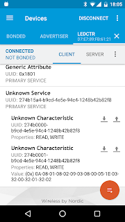


The byte array written into this characteristic is a blob that describes the light effect. The blob has two identical sections, each of them 9 bytes long. One section starts with 1 byte for the repetition counter then 4 times 2 bytes, each 2 byte subsection having 1 byte for the time duration (in 0.1 sec units) and one byte for the bit mask of the LED strips (bit 0->1 if LED strip #1 is to be on, bit 1->1 if LED strip #2 is to be on).

Regarding the Android application, there are no too many surprises. I used the now deprecated TabActivity because I did not feel like playing around with fragments for this simple prototype. The screen has separate tabs for the low- and the high-voltage strips like this:


The disconnection deficiency described in the previous post is still there. Make sure that you disconnect from the device after each manipulation (by pressing the Back button) because neither the device nor the Android application implements disconnection timeout so if you stay connected, nobody else will be able to connect to the LED strip controller. Otherwise have fun with these BLE-enabled Christmas lights!

Monday, December 19, 2016

BLE-enabled Christmas light

The idea came from the light-themed Budapest Makers' Meetup and from the cheap Christmas LED strip that my wife bought for about 1 euro. Plus my other hobby project has not gone as smoothly as expected but produced a connection-oriented nRF51822 code and bang, the idea was born, let's couple the LED strip with the Bluetooth Low Energy System-on-Chip (SoC), add an Android application and let's see what comes out of it. This post is the tale of that adventure.

First, about the LED strip. This is a battery-operated device with two states: off or on. It has surprisingly low power consumption considering its 10 LEDs.


I removed the battery case and put it away - it will serve me well in other projects. Then I hooked up the LED strip with the nRF51822 as shown in the schematics below (click to enlarge).


As described in some previous blog posts, I use a breakout board containing little more than a sole nRF51822 and the Bus Pirate programmer to upload the application into the chip. The components on the breakout board (quartz, etc.) are not shown in the schematics. If you use the same type of breakout board that I do, make sure that you connect both GNDs together otherwise instability may be the result.

Other than that, the circuit is very simple. The LED strip is driven by P0.22 of the nRF51822. Even though the strip consumes in the mA range, I played safe and inserted a 2N7000 FET between the MCU and the LEDs. The 1 Ohm resistor was already part of the circuit in its original form so I thought it is a good idea to preserve it. One can also observe the 3.3V stabilizer circuit that transforms the POWER_INPUT (5V in my case) to the 3.3V consumed by the circuit. Any stabilizer circuit will do, I just point out that without the C1 condensator I experienced instability when the Bluetooth radio was in operation. The whole circuit sits nicely in a plastic electronic enclosure box.


Now on to the software.

Click here to download the nRF51822 sources.

Click here to download the Android sources.

The programmer software that drives the Bus Pirate tool is the same forked version that we used before. The project assumes the 12.1.0 version of the nRF5 SDK. I propose that you stick to this version too because upgrading the project to another version may involve a lot of work (as I experienced previously). Convert the soft device with the convert_s130.sh script, upload into the device with the upload_softdevice.sh, compile the code with the "make" command then upload the application with the upload.sh. While doing this, you need to modify SDK path and device files in the scripts/Makefile according to the directory layout of your system. After a power cycle, you can observe the device spitting out a large amount of debug messages on the debug serial port. Also, LED1 starts flashing showing BLE advertising activity.

Before installing the Android part, let's check that the device works correctly. Download nRF Connect from the Google Play store, start scanning for BLE devices, look for "ledctr" (the default name given to our device), connect and open the custom service with the 128-bit UUID of 274b15a4-b9cd-4e5e-94c4-1248b42b82f8 that it advertises. You should see something like this:


Write the following byte array into the characteristic with the UUID of 274b0000-b9cd-4e5e-94c4-1248b42b82f8.

036000000000000360

This means 3 seconds ramp-up to 0x60 intensity (96%), no flashing, 3 seconds ramp-down from 0x60 intensity. If you see this light effect, the device is ready. Don't forget to disconnect: the application can handle only one active connection and there's no timeout mechanism implemented.

The BLE device implements the following light effect. First there is the ramp-up phase when the light intensity increases from 0 to a maximum. The ramp-up time and the maximum intensity can be set by means of BLE. Then there is the flashing phase when two states with different intensity come one after the other. The repetition counter, the length and the intensity of both states can be set. Then there is the ramp-down phase, when the intensity goes down from a maximum to zero. Here again the ramp-down time and the initial intensity can be set. All these phases are optional, if any of the time value is zero, that phase is skipped, if the repetition counter is zero then the flashing phase is skipped entirely.

The LED strip is capable of only on and off states hence the intensity effect is implemented by means of pulse-width modulation (PWM). The BLE application operates a 100 msec timer that updates the timeouts, intensity changes and state transitions. Look for the light_update_timer_handler function in main.c if you want to modify that functionality.

In order to create the Android project, follow the instructions in this blog post. Essentially you have to create an empty Android Studio project then replace the source tree under app/src with the content of the ZIP file that you downloaded previously.

The Android application has two major parts. First, it scans for BLE devices that advertise that unique UUID that I allocated to the application and lists those devices in a List. If the user clicks any of the devices, the Android application connects to the LED controller service with the unique UUID I mentioned before, retrieves the current state of the light effects and displays it by means of some SeekBars. The user can manipulate these parameters then update them on the device by pushing the "Set values" button. The device then starts to perform the light effect. The user can disconnect by pushing the "back" button.


One major deficiency of the application is that disconnection timeout was not implemented, neither in the device part, nor in the Android application. This means that the user has to take care that he/she disconnected from the device after modifications to the light effects were done. If that does not happen, the device stays forever in "connected" state which means that it will be impossible to connect to it again without resetting the device. I leave this exercise to the interested reader. :-)

The other problematic part is the lack of security. Anyone knowing how to connect to the device (either by knowing the format of the light effect blob or by just simply having the Android application installed) can manipulate the light effect. Personally I don't think it is a major issue because security can always be added later. Beside, what could possibly go wrong if a passersby can just change the light effect in my window?

Tuesday, October 18, 2016

Android phone as weather station with improved sensor

The previous two posts introduced a BLE-enabled weather sensor (temperature and humidity) and the Android application that extracts data from this sensor. I hinted that I intend to proceed with a more sophisticated sensor, Bosch Sensortech's BME280 but other projects diverted my attention (shameless self-promotion: read this paper about microcontrollers, image processing and low-power wide area networks if you are curious, what kind of projects took my time). But I never forgot my BME280 temperature/humidity/pressure sensors sitting in my drawer and once I had a bit of time, I resurrected the project.

The idea is the same as with the DHT-22. The nRF51822 combined ARM Cortex-M0 microcontroller/Bluetooth Low Energy radio unit will make the sensor data available over Bluetooth Low Energy (BLE) access. The smartphone will read this data and display it to the user. Later (not in this post) I intend to upload the data into some web service for analysis. We have already done this with the DHT-22, now we extend the sensor range with the BME280.

Click here to download the Android application. Click here to download the nRF51822 projects that are running on the sensor hardware.

Let's start with the sensor. Below is the schematic for the hardware (click to enlarge).


The difference between this and the previous one is that the DHT-22 was connected to a simple GPIO pin while the BME280 uses the more sophisticated I2C bus. As the BME280 is quite miniature, I used a breakout board for the sensor too. LED1 and the serial debug port are optional (but quite useful). Debug messages are emitted to the serial port, you need a 3.3V-to-RS232 converter on the TxD pin if you want to observe those.

As described previously, the circuit is realized with a low-cost nRF51822 breakout board and is programmed with the Bus Pirate programmer, adapted to nRF51822 by Florian Echtler. The only thing I changed in this setup is that this time I moved the projects to the latest version of the SDK which is the 12.1.0. Also, the soft device (the program module implementing the BLE stack) was bumped from S100 to S130. These decisions caused quite a headache because there's significant difference between the old SDK and the 12.1.0. Therefore I decided that in the nRF51822 project file I share not only the sensor project (called adv_bme180) but two simpler ones (blinky_new and blinky_new_s130) as additions to the instructions on Florian's page. As a recap: the soft device need to be flashed into the device before any BLE application is flashed and the starting address of the BLE application depends on the size of the soft device. This has changed between S100 and S130, hence the updated projects. In both blinky_new_s130 and adv_bme280 you will find the  convert_s130.sh and upload_softdevice.sh scripts that convert into binary format and flash the S130 soft device that came with the Nordic SDK.

Once you uploaded the S130 soft device, compile the project in adv_bme180 and upload it into the nRF51822. The sensor node works the same way as the DHT-22 version. The MCU in the nRF51822 acquires measurements from the BME280 by means of the I2C bus (called Two-Wire Interface, TWI in the nRF51822 documentation), once in every second. This includes temperature, humidity and pressure. Then the measurement values are compensated by the read-only calibration data also stored in the BME280 that the MCU reads in the initialization phase. The BME280_compensate_T, BME280_compensate_P and bme280_compensate_H functions come from the BME280 user's manual. The result is the compensated temperature, humidity and pressure values that the MCU puts into the BLE advertisement data. The advertisement data also contains the nRF51822's unique ID that is used to identify the sensor. The sensor has no name as the measurement+ID data is now too long to allow sensor name info too, BLE readers now recognize the sensor purely by its unique UUID.

Now on to the Android part. The architecture of the application is pretty much the same as described in the previous post. Creating an Android Studio project works the same way as described there: create an empty Android Studio project, write over the app/src/main subtree with the content of the archive that you downloaded from this post and update app/build.gradle file with the GraphView dependency.

The BME280 functionalty was inserted in three places. First, BME280 data has its own data provider (BME280SensorDataProvider.java). This new provider is able to handle pressure data that DHT-22 measurements don't have. BLESensorGWService properly recognizes BME280 sensor nodes beside the DHT-22 sensor nodes (so both are handled), parses BME280 advertisements and puts the measurement data into the BME280 data provider. MainActivity knows about the BME280 data provider, uses its data to create the sensor list and invokes BME280GraphMeasurementActivity if the sensor in question is BME280 sensor. This new visualization activity has pressure graph too.

This is how the sensor list looks like with a DHT-22 and a BME280 sensor (DHT-22 does not have pressure data, BME280 does).


And this is how the pressure graph looks like in the BME280 visualization activity.


And at last, some words about the deployment. I got a question, how the power supply works. After more than half a year of operation, I ended up with a discarded 12V motorcycle battery as power source. This battery used to have 6Ah capacity, now it has about half which is not enough to feed a motorcycle but is quite enough to yield 1-2 mA per sensor node for a long time. Also, this battery is designed to withstand quite severe weather conditions. I can only recommend discarded but still functional motorcycle/car batteries as power source if the place available for the sensor permits it.

Here is how the BME280 sensor looks like in its protective plastic box. The small panel in the foreground is a cheap DC-DC converter (not shown in the schematics) which makes the step-down from 12V to 3.3V.


And here is how the sensor nodes sit in an outdoor box with the battery. The lid of the BME280 node is removed for demonstration, the other box contains the DHT-22 sensor.


Now the part that is really missing is the data upload/data analysis functionality. 

Wednesday, March 2, 2016

Android phone as weather station

The previous post was about a low-cost Bluetooth Low Energy sensor (really, one sensor unit that includes the BLE-enabled microcontroller too costs less than 15 USD and that's just a single prototype, economies of scale come on top of that) and its accompanying Android app that allows obtaining sensor reading manually. That's not bad but manually reading data is sort of inconvenient. If you want to know, what the temperature and humidity was in the dawn, you have to be awake in that early hour. Personally, I prefer to sleep then so I decided to automate the whole process.

Click here to download the sources of the Android application. The content of the archive is the app/src/main subtree of an Android Studio project. In addition to extracting the sources into the app/src/main subtree, update app/build.gradle like this:

dependencies {
    compile fileTree(dir: 'libs', include: ['*.jar'])
    testCompile 'junit:junit:4.12'
    compile 'com.jjoe64:graphview:4.0.1'
}


The project depends on Jonas Gehring's GraphView project, hence this new dependency.

So what can we expect from this new app? In case of the app that came with the sensor in the previous post, you started a manual scan and if the sensor was in range, you got the humidity/temperature data. The new app scans and stores data in the background. Once it is started, it sets up a periodic timer (default timeout is 1 hour but can be changed in the settings menu) and when the timer fires, it makes a scan. If it finds a BLE node whose advertisement fits our criteria (e.g. it advertises services with the UUID I allocated) then it extracts the measurement data from the advertisement message and stores it in a database on the device. This variant does not yet upload the data to a server, that may come later. However, it can visualize the measurements on simple graphs, hence the dependency on GraphView. Like this:


Let's see the interesting bits of this app.

First and foremost, it is an interesting feature of this application that the BLE layer is used in such a way that reading the sensor is not an extra cost for the sensor. As the measurement data is embedded into the advertisement packets that the device broadcasts anyway, it does not matter if 1 or 1000 phones read and store data. So this sort of sensor network can grow into an entire ecosystem - the more phone users install and use the app, the more precisely the measured quantity will be available once the phones upload their catch to the server.

If you observe, how the data is stored (DHT22SensorDataProvider.java), you can recognize an important shortcut that I made: the database structure depends on the sensor being used. This provider depends on the fact that DHT-22 (the actual measurement device) provides temperature and humidity data in the same reading. A different sensor (like the Bosch BME280 sensors sitting in my drawer waiting for their turn) will require a new provider and also a modification of the visualization part. So there's significant development potential in making the app more flexible when it comes to adding a new sensor type.

The actual sampling of the service happens in BLESensorGWService using the AlarmManager to trigger the scan. Now getting the device awake if it was just sleeping is not a simple business. Observe in the list below, that even though there's always an hourly reading, there's a significant variation when the reading happens.


In case of our weather reading, it was not a problem but some sensors may have more variable data. A large number of devices reading and uploading would solve the problem of reading time variations.

GraphMeasurementActivity is the activity that depends on Jonas Gehring's GraphView.  The graphs are very simple so if you have another favourite graph view component, just replace it there.

So we are at the point that we added sensors to our Android device using Bluetooth Low Energy and created an application that samples them producing nice weather-related data series. The next step will be the integration of a cloud-based data analysis. I am still thinking, which one to go for.

And finally, the picture of the sensor, in its "weather-resistant" box.


Tuesday, February 2, 2016

Thermometer application with nRF51822 and Android

I built quite many prototypes on this blog with RFDuino based on Nordic Semiconductor's nRF51822 and I can still recommend that small development board to people who want to get initiated quickly and painlessly into the world of Bluetooth Low Energy programming. The limitations of RFDuino became apparent quite soon and it was time to get deeper. On the other hand, I wanted to stay with the excellent nRF51822 so I looked for a breakout board - as simple as possible.

This is how I stumbled into Florian Echtler's page about low-cost BLE development environment based on the nRF51822 and the Bus Pirate programming tool. So I quickly ordered a no-name variant of Waveshare's Core51822 breakout board, a Bus Pirate tool and a bunch of DHT-22 sensors (because I wanted to measure something in the environment). Also note that the breakout board has a connector with 2 mm pin spacing which is not the usual 0.1 inch pitch. It helps if you have a prototyping board with both 2 mm and 0.1 inch pitch like this one which cannot be found in every store.

Generally speaking, following the instructions on Florian's page was easy enough. I ran into two issues. First, I had no success with the SWD programming software he refers to but Florian's fork (which is based on an earlier version of the programming software) worked well for me. Second, I experienced instability if the GND pins of the breakout are not connected (there are 2 of them).

First about the hardware. The schematic below show only the parts that are connected to the pins of the breakout board, the schematic of the breakout board itself is not included.


Highlights:


  • DHT-22 is connected to P0.17 which is both input and output depending on the communication phase.
  • P0.21 LED provides a feedback about the BLE activities. This is a convention coming from the PCA10028 dev board that we lied to the Nordic tool chain that we have. You can omit this LED if you want to save some energy.
  • SV1 header is a TTL serial port where the example program emits some debug messages. You can omit this header if you are extremely confident. I use a level converter like this to connect this port to a standard RS232C port. The UART operates on P0.18 (RxD) and P0.20 (TxD).
  • SV2 header goes to the Bus Pirate. Check out Florian's document about the connection. Make sure that this cable is as short as possible.
Here is how the board looks in all its glory, the Bus Pirate and the RS232C level converter boards in the background. These are of course not needed for deployment, the board runs standalone after the testing is successful.


Click here (adv_dht22.zip (nRF51822), bledht22.zip (Android)) to download the example programs related to this blog post.

Let's start with the code that goes into the nRF51822 which can be found in adv_dht22.zip. The assumption is that you completed Florian's instructions, including the upload of the S110 soft device. Then unzip adv_dht22.zip and do the following modifications:

  • Edit Makefile and make sure that the RF51_SDK_PATH variable points to the location where you installed the Nordic SDK.
  • Edit upload.sh and make sure that the paths point to the location where you installed Florian's version of the SWD programmer. Also, make sure that the USB device is correct (/dev/ttyUSB0 by default).
Now you can say "make" and then "upload.sh". If all goes well, the code is installed in the nRF51822 and you get debug messages on the serial port. At this moment, the nRF51822 is already advertising the measurements it obtained from the DHT-22 sensor. You can check the content of the advertisements with this test tool.

The code looks quite frightening compared to the super-simple RFDuino equivalent but most of it is just template. My highlights:
  • Check out in advertising_init(), how the advertisement packet is set up. We transfer the measurements in a service data GAP field and I took the liberty to allocate a 16-bit UUID for it (quite far from the standard service UUIDs).
  • Check out timers_init(), timers_start() and sampler_timer_handler() methods how the periodic reading of the sensor and the update of the advertisement packet is accomplished.
  • DHT-22 sensor handling is done in dht22.c. This sensor has a somewhat peculiar 1-wire interface. Read this document and the code will be easy to understand.

Regarding the Android code: this is just the app/src part of the source tree of an Android Studio project. I adopted this rather primitive export method as this super-advanced IDE still does not have code export option that its obsolete predecessor, the Eclipse IDE used to have. Check out onLeScan method in MainActivity.java to see, how the BLE GAP parser introduced in this blog post is used to take apart the advertisement message and filter BLE nodes that advertise DHT-22 measurements.

The outcome looks like this:


Note that each sensor is identified by a 64-bit unique ID (a service of the nRF51822). Now this data just needs to be uploaded into some sort of service and then the big data analysis can start ;-). More about that later.

Wednesday, December 30, 2015

Infrared-to-Android gateway implementation with interrupts

In the previous parts of this series the infrared-to-Android gateway based on the RFDuino hardware and an improved version of the hardware were presented. The improved hardware offered quite reliable IR code recognition even when the BLE connection was in operation. Trouble with that implementation was the polling nature of the code; even though the IR reader support hardware is capable of raising an interrupt when a new time measurement is available, the code did not handle that interrupt, instead it polled the interrupt signal.

Click here for the updated gateway code. Click here for the (unchanged) Android application serving the gateway.

The reason I did not implement proper interrupt handling was the I2C library (called "Wire") coming with the RFDuino. Even though the nRF51822 (on which the RFDuino is based) is able to handle its I2C interface (called TWI, two-wire interface) by means of interrupts, it was not implemented in the "Wire" library. When the MCP23008 GPIO port extender raised an interrupt, the MCU was expected to read the MCP23008's capture register by means of an I2C transaction. As the "Wire" library was polling-based, this transaction held back the GPIO-handling interrupt for too long time, freezing the system.

The solution was transforming the "Wire" library into interrupt-based implementation. Now as my goal was a limited functionality (reading one register of an I2C periphery) I did not do it properly. I moved the entire "Wire" library into the application project (see it under the "lib" directory), renamed it to "Wire2" and introduced a couple of new methods, more importantly sendReceiveInt (in lib/Wire2.cpp). This method initiates the write transaction of a data array followed by a read transaction of another data array over I2C, all handled by TWI interrupts. This means that sendReceiveInt returns immediately and the actual data transfer happens in the background. This new method is invoked in the GPIO interrupt handler (GPIOTE_Interrupt in sketch/irblegw3.ino) but this time the GPIO interrupt handler completes very quickly as its job is only to initiate the TWI transaction handler. When the TWI transaction is finished, the TWI interrupt handler invokes the onReceive callback that ends in the application code (twi_complete in sketch/irblegw3.ino).

The most important outcome of this - quite significant - change is that the MCU does not spend its time spinning on the GPIO port reading loop. Instead, it waits for interrupts in ultra-low power mode (sketch/irblegw3.ino, IRrecvRFDuinoPCI::GetResults method, RFduino_ULPDelay invocation) which is important if the infrared-to-Android gateway is powered by a battery. As you may have guessed, my goal is not to fiddle with IR remote controllers, I intend to build a short-range network comprising of infrared, BLE and cellular links and the infrared-to-BLE gateway was just one step.

Wednesday, December 16, 2015

Improved hardware for the infrared-to-Android gateway

In the previous post I presented the results of my experiments with the nRF51822-based RFDuino as infrared-to-Bluetooth Low Energy gateway, accompanied by an Android client app. The outcome of that experiment was that the nRF51822 BLE soft stack and the purely software-based IR receiver is not a good match as the BLE soft stack "steals" enough cycles from the Cortex M0 CPU so that the IR reading becomes very unreliable no matter which implementation alternative we go for (3 different alternatives were attempted). I promised an improved hardware that overcomes this limitation and this post is about this improved hardware.

The essence of our problems with the BLE soft stack was that in case of very tight timings that the IR receiver requires, the main CPU is not suitable anymore for measuring time periods. Typical IR timing is in the 500 microsec-2 millisec range, this is the time period we should be able to measure reliably. With the BLE soft stack in operation, delays are introduced into the time measurement code by the background interrupt routine serving the soft stack and time measurement of this precision will be wildly off. I considered two options.

  • The most evident option is to drop the integrated MCU-BLE radio combo that the nRF51822 is and go for a separate MCU-BLE modem option. For example an Arduino Pro Mini with a BLE121LR modem would have been a perfect fit as there are both of these modules in my drawer. While this hardware would have been definitely more hassle-free than the nRF51822, setting it up would have required two different programming tools (I have both but that's not necessarily true for the general blog reader out there) and I am still uneasy about soldering the BLE121LR - those pads are smaller than my capabilities.
  • Extending the RFDuino with a dedicated hardware for time period measurement sounded more attractive for me as this was less evident. The functionality we expect is that the MCU is not doing any time measurement. The external hardware must be capable of measuring the time periods between the edges of the TSOP1738 output signal and deliver these measurements to the MCU. The measuring range is about 500 microsec-2 msec. Larger time periods are still measured by the MCU but in this case the disturbances caused by the soft stack are not that relevant.
Further complication is that while the nRF51822 has 31 general-purpose pins, RFDuino makes only 7 of those available and 2 of them are reserved for USB communication. This requires that the circuit is interfaced with the RFDuino with the lowest number of wires and I2C is the best option (2 wires). nRF51822 has I2C option (called TWI, two-wire interface) so this would work. I was not able to find a single-chip solution that measures and captures time periods in this time range with I2C interface but the circuit is not that complicated.


A 74HC4060 is set up as oscillator and counter. The frequency of the oscillator is about 350 kHz, yielding about 43 microsec time resolution for one counter step, making it convenient to measure between 43 microsec and 5.5 sec with 7-bit resolution. An MCP23008 GPIO-extender with I2C interface provides the conversion to I2C two-wire connection and also has a capture logic. This means that whenever the output level of the IR receiver changes, the MCP23008 stores the current value of the counter in its capture register and raises an interrupt. This way the MCU is not doing any time measurements and the time measurement hardware is able to survive about 1 msec autonomously without service from the MCU.

Click here to download the schematic in Eagle SCH format.

Click here to download the updated RFDuino gateway sources.


As with the previous version, edit the Makefile in the irblegw2/sketch directory and update the RFDUINO_BASE_DIR and the AVRDUDE_COM_OPTS variables according to the layout of the file system and the USB port mapping of the RFDuino USB shield. Then you can simply say "make upload" and the gateway is installed into the RFDuino. The Android client code and its usage is unchanged, check it out in the previous post.

The gateway code represents a step in the right direction. The I2C support library ("Wire") coming with the RFDuino gets stuck when invoked from interrupt handler so this time the MCP23008 interrupt signal is handled by means of polling. The result is that when BLE is active, occasionally there are still lost IR codes even though the quality of the recognition has improved considerably.  I intend to turn the I2C access interrupt-driven but that requires going deep into the nRF51822 that I was not yet able to accomplish in this iteration.

Friday, December 4, 2015

Controlling Android device with an infrared remote

I came across several posts about microcontrollers decoding signals of infrared remote controllers and started to think, how an IR remote can be integrated with an Android smartphone. This post is about a simple use case when I control the media volume of the Android phone with an IR remote.

Long time ago, in a distant galaxy, IR transmitter-receiver was a standard feature of almost any mobile phone. Technological progress has eliminated that feature so we are now forced to build some hardware. We need infrared sensor for sure to capture the remote's infrared signal. But how can we connect that to the phone? Last year's experiments prompted me to choose Bluetooth Low Energy (BLE). Also, the microcontroller platform was determined by my experiences with RFDuino and I happened to have an RFDuino set in my drawer.

The idea is the following. An infrared receiver is connected to the microcontroller that captures and interprets the infrared signals. If the phone is connected to the BLE radio, then the key codes sent by the IR remote are then sent to the phone over BLE. The phone does whatever it wants with the key codes, in my example the volume up, down and mute buttons are handled and are used to influence the volume of the music played by the media player.

The infrared implementation is based on the excellent IRLib code. IRLib assumes that the IR receiver is connected to one pin of the microcontroller so I built the circuit below. A TSOP1738 IR receiver is directly connected to a GPIO pin of the RFDuino which is expected to do all the decoding. SV1 header is only for monitoring debug messages, it is not crucial for the operation of the gateway. If you intend to use it, connect an RS232C level converter similar to this one.


Then came the complications. "Arduino code" is used with great liberty on the internet, as if Arduino meant a single platform. But in reality, Arduino is a very thin layer on top of the underlying microcontroller. Most of the code, tools and articles out there are based on Atmel's extremely popular AVR family of MCUs. These are 8-bit CPUs, equipped with a host of peripherials. The challenger in this domain is not Intel but ARM's Cortex family. RFDuino is a Nordic Semiconductor's nRF51822 System-on-Chip (SoC) which is a Cortex-M0 core with integrated 2.4 GHz radio. BLE is supported by means of a software stack. ARM Cortex is not supported as well as AVRs by the Arduino community and this miniproject is a cautionary tale about this fact.

Click here to download the RFDuino project. In order to compile it, you need to install the Arduino IDE with the RFDuino support as described here.

For starter, the Arduino Makefile I used with such a great success previously does not support Cortex-based systems, only AVRs. A short explanation: I don't like IDEs, particularly not in a project where I would like to see exactly what goes into the compile/link process. Arduino IDE is nice for beginners but is a very limiting environment for more ambitious projects. After several days of heavy modifications, I adapted this makefile to the ARM Cortex tool chain of the RFDuino. Go into the irblegw/sketch directory, open the Makefile and look for the following line:

RFDUINO_BASE_DIR = /home/paller/.arduino15/packages/RFduino

Adapt this according to the layout of your file system. Then type "make" and the entire code should compile. "make upload" uploads the compiled code into the RFDuino, provided that the port (AVRDUDE_COM_OPTS =  /dev/ttyUSB0 in the Makefile) is also correct.

Then came further complications. The IRLib code is also AVR-specific. The differences between Cortex-M0 and AVR are mainly related to interrupt handling, on-chip counters and GPIO options. Polluting the original code with ARM-specific fragments seemed too confusing so I rather disabled the AVR-specific parts if the code is compiled on ARM architecture and implemented the ARM-specific functionality in Cortex-specific subclasses (in sketch/irblegw.ino). There are three implementations (like in the base library) IRrecvRFDuino (which uses 50 microsec periodic interrupt to sample the IR receiver input), IRrecvRFDuinoLoop (which is purely polling-based with no interrupt support) and IRrecvRFDuinoPCI (which sets up an interrupt to detect when GPIO02 changes state). This line determines, which one is used:

IRrecvRFDuinoPCI My_Receiver(RECV_PIN);

And now the biggest surprise. If BLE is not active, all the three implementations work. But if BLE is active, the software stack running behind the scenes on the RFDuino steals enough cycles so that IR reading becomes completely unreliable. The best result is provided by IRrecvRFDuinoPCI (which is activated in the download version) but even that version, after a significant loosening of the matching rules drops about 1 IR key out of 4. Well, folks, that's what I could achieve with this hardware and that's the second important take-away: SoCs with integrated communication stacks (this time BLE, but can be WiFi, GSM, whatever) are notoriously tricky if the sensor processing logic is time-critical.

Click here to download the Android code. To decrease download size, I packed only the files under the app/src/main directory of the Android Studio project.

The Android implementation is quite self-explanatory and is heavily related to this earlier RFDuino example program. This time I wanted to make sure that once the gateway is connected through BLE, the application can be sent to the background so I implemented the BLE connection logic in a service that significantly complicated the code. But after all this wizardry with Android services, the important part is here in IRGWService.java:

if( v == IR_KEY_VOLUME_PLUS ) {
     audioManager.adjustStreamVolume(  
                AudioManager.STREAM_MUSIC,
                AudioManager.ADJUST_RAISE,
                AudioManager.FLAG_SHOW_UI);

...

This is the fragment that maps IR remote keys to actions on the phone. The RFDuino-based gateway does not do any key mapping so it is the Android application that needs to know the meaning of the IR key codes. The following comes from the Philips remote I grabbed for these experiments.


    private static final long IR_KEY_VOLUME_PLUS = 0x20df12edL;

It is highly likely that you will have to change this value according to your remote's key code map. Just press the desired button and check the code.


This project was not a complete success as IR reading is not as reliable as it should be. But it is indeed fun to control the Android phone with an ordinary IR remote. I plan to improve the hardware a bit to make key recognition better so stay tuned (if you care about IR remotes).

Update: check out the follow-up blog posts (this and this).

Tuesday, December 30, 2014

Integrating an Android smartphone application with the BLED112 module

My conclusion with the RFDuino adventures was that RFDuino is a perfect platform to start familiarizing with the Bluetooth Low Energy (BLE) technology. BLE programming was made so simple with RFDuino that it provides quick success. Simplification comes with limitations, however, and eventually time has come for me to step further toward a more flexible BLE platform. Bluegiga's BLE121LR long range module seems to have outstanding range but first I tried a piece of hardware that is equivalent from the API point of view with the BLE121LR but is easier to start with and that is Bluegiga's BLED112 USB dongle.


The BLED112 implements the same API (called BGAPI, check out Bluetooth Smart Software API reference) that other Bluegiga BLE modules do but there's no need to buy the pricey DKBLE development board or build any hardware. It plugs neatly into the USB port and is functional without any additional piece of hardware. From the serious BLE application development perspective it has drawbacks too. Firstly, its USB interface is drawing a constant 5mA current so this solution is not very much "low energy". Second disadvantage is that its single USB interface is shared between the BGAPI API and the programming interface so installing scripts into the BLED112 is a risky enterprise. If the script running on the BLED112 occupies the USB port, there's no way to update it so the module is essentially bricked. Hence in this exercise we will keep the BLE application logic on the PC hosting the module and talk to the module with BGAPI. This is very similar setup when the application logic is running on a microcontroller or embedded PC.

Click here to download the Android client and the PC server example programs.

In this exercise, we will implement the Current Time Service (CTS) and access this service from an Android application. CTS is a standard Bluetooth service. The PC application will fetch the current time from its clock and will update the characteristic exposed by the BLED112. The Android application will detect the advertised CTS service, connect to it, retrieve the time and display it to the user. The Android application will also subscribe to time changes demonstrating the notification feature of BLE GATT.

Let's start with the PC part. Unpack the cts_example.zip file and inside there are a set of C files belonging to the PC application in the root directory. I developed and tested the application on Ubuntu 14.10 so if you use a similar system, you have good chances that you just type "make" and it will compile. Preparing the BLED112 dongle is more complicated, however and this is the result of the quite cumbersome Bluegiga tool chain. Any change to the GATT services (read this presentation if you don't know what GATT is) requires a firmware update of the BLED112. This sounds scary but it is not too complicated if you have a Windows system. Bluegiga SDK supports only Windows and there is one element of the tool chain, the firmware downloader that does not run on emulated Windows either - you need the real thing. So the steps are the following:

  • Grab a Windows machine, download the Bluegiga SDK and install it.
  • Get the content of the config subdirectory in cts_example.zip and copy somewhere in the Windows directory system. Then generate the new firmware with the <bluegigasdk_install_location>\bin\bgbuild.exe cts_gattBLED112_project.bgproj command. The output will be the cts_BLED112.hex file which is the new firmware. We could have placed application logic into the firmware with a script but as I said, it is a bit risky with the BLED112 so this time the new firmware contains only the GATT database for the CTS service.
  • Launch the BLE GUI application, select the BLED112 port and try to connect by clicking the "Attach" button. If all goes well, you will see green "Connected" message. Then select Commands/DFU menu item, select the HEX file we have just generated, click on the "Boot into DFU mode" button. One pecularity of the BLED112 that in DFU mode it becomes logically another USB device so the main window will display red "Disconnected" message.  Then click "Upload". If the upload counter reaches 100% and you see the "Finished" message, the firmware update is done.
At this point we are finished with Windows and can start the serious business. Plug the dongle into the Ubuntu machine and check out its port.

dmesg | tail
...
usb 3-2: Product: Low Energy Dongle
usb 3-2: Manufacturer: Bluegiga
usb 3-2: SerialNumber: 1
cdc_acm 3-2:1.0: ttyACM0: USB ACM device


So this time the dongle is mapped to /dev/ttyACM0. Launch the BLE server with the following command:


./conn_example /dev/ttyACM0


The server is ready, let's see the Android client. Import the Android project in CTS.zip into Android Studio. Note that I am still baffled by the fact that this shiny new IDE does not have a project export command so I had to zip part of the project's directory tree manually. Once you launch the Android application, you will see a screen like this:


The device named "test" is our device and the CTS service is identified by the UUID of 0x1805. The other entry is just another BLE device that I threw in for demonstration. Click on the device name and you get the time emitted by the BLE dongle:


The current time is also updated every second demonstrating that the client successfully subscribed to the changes.


On the server side, it is important to note that the BGAPI protocol is defined in terms of byte arrays sent and received over the serial port (which is mapped to USB in the case of BLED112). The BGAPI support library coming from Bluegiga that I used in this demo is just a wrapper over this interface so it can be replaced with an optimized implementation if the library is too heavy for the application platform (e.g. for a microcontroller) or is not implemented in the desired language (e.g. in Python). On the Android client side, it is interesting to note how the BLE advertisement parser library I presented in this post is used to figure out, whether the device advertises the CTS service we are interested in.

Friday, December 19, 2014

Parsing BLE advertisement packets

Ever since I created the Gas Sensor demo (post here, video here, presentation here), I had the feeling of an unfinished business. That demo sent the sensor data in BLE advertisement packets so the client never connected to the sensor but received data from the sensor in a broadcast-like fashion. The implementation looked like this:

        public void onLeScan(final BluetoothDevice device, int rssi, byte[] scanRecord) {
            String deviceName = device.getName();
...
                int addDataOffs = deviceName.length() + 16;
                int siteid = ((int)scanRecord[addDataOffs]) & 0xFF;
                int ad1 = ((int)scanRecord[addDataOffs+1]) & 0xFF;

This was a quick & dirty solution that remained there from my earliest prototypes. It sort of assumes that the structure of the BLE advertisement packet is fixed so the sensor data can always be found at fixed locations of the advertisement packet. This does not have to be the case, Bluetooth 4.0 Core Specification, Part C, Appendix C (or Core Specification Supplement in case of 4.2 version) describes, how the fields of the advertisement packets look like. It just so happens that with the given version of the RFDuino BLE module, the Manufacturer Specific Data field where RFDuino puts the user data for the advertisement packet can always be found at a specific location.

The proper way is of course to parse this data format according to the referred appendix of the specification and in this post I will show you how I implemented it.

Here are the three example programs mentioned in this post: blescan.zip, gassensordemo.zip, gas_adv.ino

Let's see first the BLEScan project.

Update: the project has been updated to support more of the 4.2 elements. It has also been converted into an Android Studio project but the download material contains only the app/src part of the tree.

Update: I was asked by e-mail, how to import the project (in blescan.zip) into Android Studio. Here is a simple process.
  • Create a new project in Android Studio under any name. Make sure that your project supports at least API level 18. Choose the "create no Activity" option.
  • Once your project is created, go and find it on the disk. On my Ubuntu system, the project files go under ~/StudioProjects/<ProjectName> where <ProjectName> is the name you gave to your project. We will call this directory <ProjectDir>.
  • Go into <ProjectDir>/app/src and delete everything there. Copy blescan.zip into <ProjectDir>/app/src and unzip it. It will create a single directory called "main" and the sources below.
  • In Android Studio, do File/Synchronize. After that is completed, you can open your project files, build APK, etc.

The parser code is under the hu.uw.pallergabor.ble.adparser package. Then you just give the scanRecord array to AdParser's parseAdData method like this:

            ArrayList<AdElement> ads = AdParser.parseAdData(scanRecord);

and then you get an array of objects, each describing an element in the scan record. These objects can also produce printable representation like this:


Now let's see the revised GasSensorDemo project, how the gas sensor measurement is properly parsed out of the scan record. First we parse the scan packet fields:

                ArrayList<AdElement> ads = AdParser.parseAdData(scanRecord);

Then we look for a TypeManufacturerData element which corresponds to a Manufacturer Specific Data field in BLE. We make an extra check to make sure that the manufacturer field in the Manufacturer Specific Data is 0x0000 because RFDuino always creates a Manufacturer Specific Data field like that if the application programmer specifies additional advertisement data.

                    AdElement e = ads.get(i);
                    if( e instanceof TypeManufacturerData ) {
                        TypeManufacturerData em = (TypeManufacturerData)e;
                        if( em.getManufacturer() == 0x0000) {


It would be tempting to use a custom manufacturer field or better, a Service Data field. But then we run into another limitation of RFDuino because RFDuino with its default firmware is only able to create advertisement packets like in the previous example. This is not bad because it allows the programmer to achieve quick success but later on, we will need more flexibility and that will need another BLE module.

Friday, November 21, 2014

Motor boat control with Bluetooth Low Energy

 My previous post about Bluetooth Low Energy applications with RFDuino and Android presented a connectionless gas sensor. That prototype was based solely on BLE advertisements, no connection was built between the scanner device (Android phone or tablet) and the sensor. While this connection-less operation is advantageous for sensors that just broadcast their measurement data, more complex scenarios that e.g. require authentication or build a communication session cannot be implemented in this model. The prototype I am going to present in this post demonstrates connection-oriented operation between RFDuino and an Android application.

Watch this video to see what the application is about.


The story behind this motor boat project is that I bought this RC-controlled model boat while I worked in the UK. But when we moved back to Hungary, I lost the RC controller. So the boat had been unused for years until I realized how great it would be to use an Android device as a controller. Hence I quickly integrated the RFDuino with the motor boat's original control circuitry and wrote the necessary software. As you can see in the video, it has quite respectable range even though I did not dare go into the October water of Lake Balaton where the second part of the video was shot (water temperature: some 10 degrees centigrade).

First about the "hardware". I did not have the circuit schema of the original RC controller in the boat so I had to experiment a bit. By following the motors' cables I quickly found two three-legged stocky elements that looked like switching transistors (although the labels on them were not readable after all those years in service). I removed one end of the resistors that I thought connected the base of these transistors to the rest of the RC control circuit and tried out, how much current is needed to switch on the motors. To my pleasant surprise, 1 mA current was enough so I rather believe that these are actually not transistors but power switching ICs. Anyway, RFDuino outputs can provide 1 mA switching current so I just connected the other end of those removed resistors to two spare RFDuino I/O ports. Lo and behold, it worked. If RFDuino raises any of these pin to 1, the respective motor starts. One minor additional problem was about the power supply of RFDuino. The motor boat employs an 7.2 Volt battery and RFDuino needs 3.3 V. I added an LM1117-3.3V power regulator circuit between the battery and RFDuino and the "hardware" was ready.


Do you know about BLE concepts like service and characteristics? If not, please read this presentation for a quick introduction. In short: BLE services (also called GATT profiles) are composed of characteristics which are key-value pairs decorated by meta-information that the BLE specification calls descriptors. RFDuino with its default firmware is not able to implement any standard GATT profile except for its own custom GATT profile. This is a major disadvantage in product-level development but makes RFDuino code super-easy because the programmer does not have to deal with BLE details. In the RFDuino custom service, a "read" and a "write" characteristic is defined. Whatever the client (in our case, the Android application) writes into the "write" characteristic appears for the RFDuino code as incoming data callback. If the RFDuino code calls the RFduinoBLE.send(v) method, the data appears in the "read" characteristic. The Android client can register a callback for data manipulations of the "read" characteristic so it will receive callbacks when RFDuino code invokes the RFduinoBLE.send() method. There are additional callbacks for service connections and disconnections.

You can download the Android project and the RFDuino source here.

First about the RFDuino code.  Beside the familiar setup() and loop() functions, you will see three functions characteristic to RFDuino. RFduinoBLE_onConnect() is called if a client connects to the RFDuino BLE service, RFduinoBLE_onDisconnect() is called on disconnection and RFduinoBLE_onReceive() is called when there is incoming data. There is only one complication in the code that requires explanation: this is a powerful motorboat and it can go out of BLE radio range very quickly. In the early versions the boat became uncontrollable in this case meaning that it just continued with the last command received. That was not a nice feature so I implemented a heartbeat message feature which is sent in every 5 second. The loop() method starts by sending the heartbeat to the client and goes to sleep. It wakes up after 5 seconds and if it finds that the client did not send back the heartbeat, it stops the motors. Otherwise the client just sends a bit mask about which motors to stop or start and the RFDuino just responds with the same mask informing the client that the motors were indeed started or stopped. This means that the arrows on the user interface showing which motors are running represent the actual state of the boat which is advantageous if something goes wrong.

Then about the Android side. The code starts by discovering the device. Once the device is discovered, we connect to the device with the connectGatt() method then discover its services with gatt.discoverServices() method. Once the service discovery callback arrives, we retrieve the RFDuino service (getService(), we expect this custom service) and obtain the characteristic handles (getCharacteristic()). We use the "read" characteristic's client configuration descriptor to enable notifications from the RFDuino server to the Android client so that we get a callback when the RFDuino side sends something to us.

Disconnection is worth detailing because there's an RFDuino speciality here. Normally, one can just disconnect from the service with the disconnect() method invocation. RFDuino however is left in a limbo state in this case: the BLE session is disconnected but the RFDuino application does not receive a callback and cannot accept a new connection request. The "disconnect" characteristic has to be written to (the value does not matter) for the RFDuino server to properly disconnect.

Monday, September 29, 2014

Gas sensor prototype explained

The "We know RFDuino" contest has not ended yet but its end is sufficiently close so that I can explain our prototype application. Our entry is a Bluetooth Low Energy-connected gas sensor and it is presented in the video below. Make sure that you watch it, you help us win the competition.


The prototype demonstrates a unique capability of Bluetooth Low Energy device advertisement messages: you can embed user data into these broadcasts. These come handy if you just want to send out some measurement data to whoever cares to listen without creating a session between the BLE client and server. This broadcast-type data transfer may support unlimited number of clients with very low energy consumption on the sensor side.

Click here to download the Android client application project.

Click here to download the RFDuino source code.

The prototype works like the following. The microcontroller presented in the video measures the Lower Explosion Limit and sends this value to the RFDuino microcontroller over a super-simpe serial protocol. A message of this protocol looks like this:

0xA5 <seq_no> <LEL%>

where seq_no is an increasing value and LEL% is the measured Lower Explosion Limit value. The microcontroller code is not shared here but you can get the idea. The RFDuino code receives the LEL% value over the serial port it creates on GPIO pins 3 and 4, creates a custom data structure for BLE advertisements consisting of the site ID and the LEL% value then starts advertising. This is performed cyclically so the LEL% value is updated in the sensor's BLE advertisement every second.

Now let's see what happens on the Android side. This is a non-trivial application with multiple activities but the Real Thing (TM) happens in the MapScreenActivity, in the onLeScan method. This method is called every time the Android device's BLE stack discovers a device. In this case we check whether the device's name is "g" (this is how we identify our sensor) and we retrieve the LEL% data from the advertisement packet.  We also handle the Received Signal Strenght Indicator (rssi) value for proximity indication. Bluetooth device discovery is restarted in every 2 seconds so that we can retrieve the latest LEL% value. The rest is just Plain Old Android Programming.

The identification of the sensor and the encoding of the sensor data is obviously very naive but this is not really the point. You can make it as complex as you like, e.g. you can protect the sensor data with a hash and place that hash also into the advertisement so that the receiver can make sure that it gets data from an authorized sensor and not a fake one. The important thing is that the entire framework is sufficiently flexible so that relatively complex functionality can be implemented and RFDuino really simplifies sensor programming a lot.

If you enjoyed the example application, make sure you watch the video (many times if possible :-)) and if you happen to be in London on 2014 November 19, you might as well come to the Londroid meetup where I present this and another BLE project (a connection-oriented one, called MotorBoat).