Saturday, March 10, 2012

Example application for accelerometer/compass processing on Android

I hope you are well prepared by now what you can expect from the compass-accelerometer sensor fusion - if not, please read my thoughts about the limitations. This time we are going to see, how to compensate the accelerometer with the compass.

The idea is very simple. The accelerometer and the compass both measure vectors fixed to the Earth. These vectors are different - gravity and ambient magnetic field - but we hope that their angle is constant because they are both fixed to the same coordinate system. But while the accelerometer is sensitive to the motion acceleration, the compass is not. If we manage to rotate and scale the magnetic field vector into the gravity vector, we have a reference while the accelerometer is subject to motion acceleration and we can extract the motion acceleration. Plus, we have a reliable gravity vector and an "in motion" indication.

So the process is the following:

  • Calibrate the compass to the location and figure out the offsets we discussed in the limitation part. Also measure the reference gravity vector length.
  • If we find that the acceleration vector's length is close enough to the reference gravity vector length, we assume that this means "no motion" (see the discussion of this issue here). Find then the rotation axis and angle to rotate the compass vector into the acceleration vector. We call these values reference rotation axis, reference rotation angle, reference magnetic vector and reference acceleration vector, respectively. Keep updating these values as long as we are in "no motion" state.
  • If we find, that the acceleration vector's length is significantly shorter or longer than the reference gravity vector length, we are in "motion" state. Then we use the previously recorded reference values and the actual magnetic field value measured by the compass to calculate a simulated gravity vector. Using the measured acceleration vector and the simulated gravity vector, we extract the motion acceleration vector.
Simple, isn't it? Yes, it is, the only part requiring attention is the rotation bit. The task is the following: we have a reference magnetic vector and a reference acceleration vector from an earlier measurement. Then the acceleration vector length was close to reference gravity so we can assume that the reference acceleration vector mostly contains gravity component. Now we have a current magnetic vector and a current acceleration vector. The acceleration vector, however, seems to contain motion acceleration component too. How to simulate a gravity vector from the current magnetic vector?

The steps are:
  • Calculate the rotation operation that rotates the reference magnetic vector to the reference acceleration vector. The rotation operation has two components: an axis around which one vector is rotated to the other and a rotation angle. The rotation axis is the vector cross product of the two vectors. The angle can be obtained by resolving the equation of two different representations of the two vectors' dot product. This yields reference rotation axis and reference rotation angle.
  • The reference rotation axis nicely rotates the reference magnetic vector to the reference acceleration vector but we need to apply the rotation to the current magnetic vector. We need a new rotation axis for this and we obtain it by rotating the reference rotation axis by the rotation operation that rotates reference magnetic vector to the current magnetic vector. This yields a current rotation axis.
  • Then we simply rotate the current magnetic vector around the current rotation axis with the reference rotation angle. This yields a simulated gravity vector. We also have to scale this vector so that its length is equal to the reference gravity.
Once we are done with this, we can subtract the simulated gravity vector from the current acceleration vector and we have the motion acceleration.

Let's see the example Android program then that implements all this!

The example program can be downloaded from here.

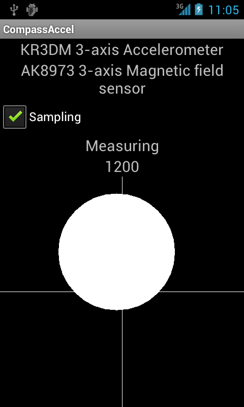
The program is really just a variation of the gyroscope/accelerometer example program. The main difference is that when the sampling is started, you have to calibrate the compass first. The application instructs you, which edge/side of the device should be turned toward the Earth and the calibration steps already passed disappear from the screen. This is really a major annoyance compared to the gyroscope version but that's the price we pay for having a widely available sensor instead of the rare gyroscope.


After the calibration you see the familiar ball that visualizes the measured motion acceleration (the size of the ball is proportional with the z component of the motion acceleration). As with the gyroscope case, the motion acceleration is rotated into the Earth's coordinate system. If you need the motion acceleration in the device's coordinate system, just remove the rotateToEarth() method invocation.

If you set DEBUG to true in SamplingService.java, the program creates a (potentially large) file containing measurement data as /sdcard/capture.csv. You can analyze it with this Sage script.

Now we have two methods of extracting motion acceleration. The gyroscope is more convenient because it is not subject to external magnetic fields or metal objects but is available in less devices. There are more hassles with the compass but at the end it works nicely too. The next step is to recognize movement patterns in the 3D motion acceleration vectors.

Saturday, March 3, 2012

PHONE_STATE broadcast and 4.0.3

Anybody out there who has experience with android.intent.action.PHONE_STATE broadcasts and 4.0.3? I wrote this simple application that is just a receiver for this broadcast intent. It works beautifully on 2.2 but does not capture any broadcasts on a Nexus S with the official Google 4.0.3 firmware. The manifest has the permission (XML mangling because of the blog engine):

    [uses-permission android:name="android.permission.READ_PHONE_STATE"/]

and the receiver:

       [receiver android:name=".PhoneIntentReceiver"
            android:enabled="true"
            android:exported="true"]
            [intent-filter]
                [action android:name="android.intent.action.PHONE_STATE" /]
            [/intent-filter]
        [/receiver]

Is this a 4.0.3 bug?

Thursday, March 1, 2012

Compensating accelerometer with the compass - the limitations

In the previous parts of our sensor processing series, we have seen how to use the gyroscope to separate the motion and the gravity acceleration components measured by the accelerometer. But gyroscope-equipped phones are rare. Can we have a "poor man's gyroscope" that is more widely deployed in today's devices?

Let's reiterate the problem. We have an accelerometer that is exposed to two main kinds of accelerations: gravity and motion acceleration. Gravity acceleration is always present. Sadly, its direction is not constant but changes with the direction of the device. If the device is subject to motion acceleration (e.g. the user is walking), motion acceleration is added to the gravity component. Motion acceleration vector changes dynamically due to the movement phases. If we have to assume that motion acceleration is present but we don't know the gravity acceleration vector, separating the gravity and motion acceleration components is impossible. We need another sensor therefore and we made a good use of the gyroscope so far.

The other evident sensor that can be used to determine the Earth's coordinate system relative to the device coordinate system is the compass or magnetic sensor. Compass is attractive because it is widely available in today's devices. Unfortunately it has certain drawbacks that make it more inconvenient to support the accelerometer than gyroscope. In this part I will go through the characteristics of the compass to set the expectations before we start to discuss, how to use it together with the accelerometer.

First the basics. The compass measures the magnetic field the device is exposed to. This magnetic field has many components. We are most interested in the Earth's magnetic field but obviously there are other disturbances, e.g. metal objects, magnets, magnetic fields generated by electric devices. The Earth's magnetic field is not trivial either. Contrary to a belief I hear often, the Earth's magnetic field points mostly downward, toward the center of the Earth. The effect is called magnetic inclination and it means that the Earth's magnetic field has a varying degree relative to the Earth's surface. Where I live, the inclination is  about 70 degrees. The component that compasses measure to find the "North" (more exactly: magnetic North) is just the x and y components of the magnetic field which are smaller than the z component.

External magnetic fields can make measuring the Earth's magnetic field virtually impossible. The graph below shows an extreme case when I started compass sampling and walked into an underground train that eventually left the station.
The x axis is the sample count (proportional to time), the y axis is the length of the magnetic field vector measured by the compass. You can see that around 1900 sample count the metal body of the train starts to show its effect. Then around 2400 the electrical traction motors of the train start to operate which generates at its peak 6 times larger magnetic field than the Earth's magnetic field. This magnetic field also varies in time as the power of the motors fall after the train is accelerated to its cruising speed. First rule therefore is to avoid large electric devices, particularly those that vary their power in time.

The compass also has characteristics that make life harder. The two diagrams below show two measurements. In each measurement the device was rotated around its y axis a full circle (see the SensorEvent documentation about device axes in Android) then it was rotated 90 degrees around its x axis and rotated fully around the y axis again. The two measurements were different only in their location. Both were performed in average rooms, relatively far from metal objects (as much as it is possible in average rooms and buildings).
We expect to see neat circles centered around the origo. What we see is that the circles are not centered around the origo but have characteristic offsets. Worse, those offsets are not the same even though the measurements were done with exactly the same device.


 In order to support the accelerometer with the compass, we have to swallow the following two limitations.
  • No magnetic fields around that vary in time (typically electric devices, trains, etc.)
  • The compass has to be calibrated at each location (by rotating the device around). This pretty much excludes measurements on the move (e.g. walking).
If these limitations are acceptable, however, then we have a reference sensor that can replace the accelerometer while the device is subject to motion acceleration and we can extract motion acceleration. We can implement those Wii-like games even if there is no gyroscope in the phone.

I tell you how in the next part.

Friday, February 10, 2012

Example application for accelerometer/gyroscope processing on Android

In the previous parts we have seen how to simulate the gravity vector with the gyroscope if the accelerometer is not able to measure gravity correctly (because it is subject to motion acceleration too beside the gravity acceleration) and how to update this simulated gravity vector from the accelerometer to prevent the accumulation of measurement errors. At the end of the previous post we had a gravity vector which was normally taken from the accelerometer but our algorithm switched to gyroscope simulation automatically when needed.

We need just one more step to enable cool applications and that step is very evident. If you remember my Droidcon 2011 presentation (slide 24), the acceleration measured by the accelerometer is the sum of gravity and motion acceleration. If both are present, they cannot be separated in the general case without additional sensor input. But now we have the gravity acceleration which is reasonably exact even if the accelerometer is subject to motion acceleration too. This means that we can extract the motion acceleration by subtracting the simulated gravity acceleration from the acceleration measured by the accelerometer.

This opens the way for applications based on dynamic movements much like the Wii games with Motion Plus accessory (which actually do the same as the Motion Plus accessory is really just a 2+1 axis gyroscope).

The example program can be downloaded from here.

After all these simulation script, let's see something hands-on. The example program is the implementation of all these ideas we have seen so far. You need an Android phone with gyroscope to test it. The gyroscope processing algorithm is implemented in SamplingService.java. GyroAccelActivity is really doing only visualization, getting callbacks from SamplingService.

When started, the service enters the calibration state. This state is necessary to get a good fix of the initial gravity vector so the device should not be moved when calibrating. The initial gyroscope drift experienced on my Nexus S also ceases during the calibration period.

Then the service enters the measuring state and implements everything we discussed so far. It samples the accelerometer and the gyroscope paralelly, simulates the gravity vector if it finds out that the accelerometer is probably subject to motion acceleration and calls back the activity with the calculated motion acceleration vector. The acceleration is shown as movement of a large white ball (quite ugly, actually). The x and the y components of the motion acceleration move the ball horizontally and vertically while the size of the ball is calculated from the z component of the motion acceleration.

Note that the motion acceleration is expressed in the coordinate system of the device itself, so you may get some unexpected result if the device is not parallel to the floor surface. As we have the gravity vector, rotating the motion acceleration vector to the Earth's coordinate system is simple exercise (took me several days to get it right ;-)). We calculate two rotations (around z and y axes) to rotate the gravity vector into the z axis. At the same time we rotate the motion acceleration vector with the same rotations. This yields a normalized motion acceleration vector that would have been measured if the device were parallel to the surface.

If you are done with playing the ball, you will notice that analyzing these 3D acceleration vectors are not trivial. You can try setting the SamplingService.DEBUG field to true, then the application produces the usual /sdcard/capture.csv file (beware, it can be large) that you can download to your computer and visualize with this Sage script.


Wednesday, January 25, 2012

Compensating accelerometer data with the gyroscope

In the previous post we have seen, how we can simulate the rotations of the gravity vector (thus measuring the exact tilt) with the help of the gyroscope. During that measurement we moved the device only slowly to validate the claim that the gyroscope is able to track the gravity vector for a certain period of time. We were aware of the fact that measurement errors for this type of measurement will eventually accumulate and therefore we have to pick the correct gravity vector time to time.

In this post we go one step further. We will use the gyro-based simulated gravity vector only if the accelerometer does not provide us with reliable gravity vector measurement (because the device is subject to motion acceleration too). But how to figure out if the gravity measurement of the accelerometer is reliable or not? Let's see the picture below which is shows the absolute value (the length) of the accelerometer's output vector as a function of sample count when the device is subject to a "tennis-like" movement. This means that the device is held in one hand and I simulated as if it was a tennis racquet. The device rotates but is also subject to a significant motion acceleration.


We have problem when the absolute value of the acceleration is significantly larger (or smaller) than 1 g (about 10 m/s^2). This means that when the absolute value of the acceleration vector is close to 1g, we can be quite sure that there is no motion acceleration and we have reliable gravity vector measurement.

This detection method is not foolproof, however. We can construct gravity and motion acceleration vector arrangements so that the length of the resulting vector is 1 g, still it points to completely wrong direction compared to the gravity vector. The keyword is "construction". Even though these arrangements are possible, it is very unlikely that they persist for a long time during motion.

So the gyro compensation algorithm is the following:

  • If the absolute value of the acceleration vector is significantly larger or smaller than 1g, ignore it and use the gyro-simulated gravity vector.
  • If the absolute value of the acceleration vector is close to 1g but differs significantly from the gyro-simulated vector then start counting these cases. If this case happens 5 times consecutively then update the gyro-simulated vector from the acceleration vector and use that.
Otherwise update the gyro-simulated vector from the acceleration vector and use this value to calculate the gravity vector.

Let's see now our racquet swing. The samples were taken with the Android application attached to the previous post, the analysis was done with this Sage script. The Sage script takes the samples from capture.csv file - you can easily change that in line 456. Blue line is the collection of 3D acceleration vectors from the accelerometer, red line is the gyro-compensated gravity vector (taken from the accelerometer if there is no motion, simulated with the help of the gyroscope if motion acceleration is detected).


As you can see, the blue line is everywhere. Actually it goes out of the coordinate system as the Nexus S has its accelerometer limited at 2g - that's why you see the acceleration curve turned into straight lines at the fastest points of the movement. The red line, however, follows the curve of the device's tilt nicely and eventually ends almost where the acceleration's blue line does. Then it gets compensated by the accelerometer's gravity vector measurement - no cumulative errors.

There's more to come, just stay tuned.

Saturday, January 21, 2012

Measuring movement with accelerometer and gyroscope

Santa Claus brought me a present and that sadly means retiring of my trusty Nexus One. Not that the phone has any problem - it still functions perfectly. As Google does not update the Nexus One anymore with new software release, I had to change. And the winner is - well, not the Galaxy Nexus, that's too expensive. I chose a Nexus S because of its attractive price, its update path toward Android 4.x (it is actually the cheapest option today of an Android 4 phone) and its built-in gyroscope.

I wanted to put my hand on a gyroscope-equipped phone for a long time. I discussed in length the problems of using only the accelerometer when identifying movements in my Droidcon 2011 presentation and I hinted that additional sensors could be used to compensate for the motion acceleration that is added to the gravity acceleration and is impossible to separate in the general case. That's what I am aiming to do with the gyroscope in this series of posts.

First let's see the problem. As you can see in slides 23 and 24 of the Droidcon 2011 presentation, there is a problem if the accelerometer is subject to gravity and motion accelerations at the same time. These are impossible to separate in the general case which corrupts both use cases. If the accelerometer is used to measure gravity (e.g. to figure out the device tilt), any motion acceleration distorts the measured tilt. If the accelerometer is used to measure motion acceleration and the exact direction of the gravity acceleration is not known, it is impossible to subtract it and the components of the motion acceleration is impossible to calculate. We need another sensor to acquire additional information to separate the gravity and motion components.

Gyroscope sensor is somewhat rare in today's Android phones. Nexus S was the first to have gyro sensor and since then some high-end phones like Galaxy S II got the sensor. If you want to play with gyro, check, whether your phone has the sensor.

The gyroscope measures angular speed along the 3 axes. As the SensorManager in Android delivers the sensor samples along with timestamps measured in nanoseconds, it is possible to calculate the rotation angle in radian by multiplying the angular speed with the time difference between the current and the previous sample. This means that we know the rotation angles along the 3 axes from the previous to the current gyroscope sample.

Thus the gyroscope can be used to replace the accelerometer when the accelerometer data is distorted by motion acceleration. If we have a reliable gravity vector measurement, we can use the rotation angles measured by the gyroscope to rotate this vector to its new position. As the gyroscope is not subject to motion acceleration, the gravity vector updated by the gyroscope rotation angles will not be affected by the motion acceleration.

The example program is available here.

How exact could this tracking be? I have made a simple sensor sampling application that samples the accelerometer and the gyroscope paralelly. If you try it out, please check that both the accelerometer and the gyroscope sensors' name is displayed - this means that they are available. Move the device only slowly - we don't want motion acceleration in this measurement. The sample file is saved in the file capture.csv on the SD card - typically /sdcard/capture.csv. Fetch this file and you can analyse it with this Sage script called gyro.py. This script expects the measurement data file in the current directory with the name of agx.csv - you can easily change it in line 244.

As the figure below demonstrates, the real gravity vector (blue line) is pretty close to the gravity vector simulated with the gyroscope (red line). Eventually the cumulative errors will make the simulated vector diverge from the real gravity vector - more about later.


Saturday, October 22, 2011

Workaround for minimizing sensor sampling battery cost

In my Droidcon 2011 presentation I tried to highlight the battery cost of the continuous sensor sampling which is necessary for detecting motion patterns. While the general case still requires some sort of improvement over the current Android sensor architecture e.g. the use of the "wake on motion" feature of the acceleration sensors, it is possible to decrease the battery consumption if the motion to be detected is longer than 5-10 seconds. This is still not suitable for recognising very short events like fall, tap, shake, etc. but can be suitable to "wake up" a step counter when the motion starts. Some steps would be missed but this may be acceptable if the battery life is increased.

Click here to download the example program.

The essence of the workaround is to use the AlarmManager and to generate periodic wakeup events. When the wakeup event is received, sensor sampling is started and some samples are collected. Then we have to figure out using some heuristics whether there is some movement. This implementation calculates the average value of the acceleration sample absolute values and looks for values deviating from the average. If there is movement detected, the sampling continues. If there is no movement detected, the program gives up the wake lock and goes back sleeping.-

I have made some measurements using my Nexus 1. I switched the phone into airplane mode and ran the program during the night, for 7-8 hours. The battery percentage consumed during an hour can be seen below as a function of wakeup period (check out WAKEUP_PERIOD constant in AlarmSleep.java).

5 sec - 1.14%/hour
10 sec - 1.10%/hour
20 sec - 0.56%/hour
30 sec - 0.27%/hour

The battery consumption with the last timeout value - 30 sec - is very close to the standby consumption, 0.25%. If you can tolerate that long "dead period", then you can bring the battery consumption in "no motion" state very close to the phone's normal standby consumption. For a general "tap" or "shake" detector, however, this is not an adequate solution. I have received encouraging mails that a proper solution relying on the sensor's low-power mode may be deployed soon.