Thursday, April 12, 2012

3D transition animation between Activities

I have got a question in this post on the Sfonge site whether it is possible to create a 3D transition effect between two Activities. There is a sample program that does it among the API Demos but this program plays the transition effect between two views of the same Activity. The adaptation to do the same between two activities is not very complicated but has some tricks, that's why I decided to publish this example program.

Click here to access the example program.

First and foremost, I unashamedly stole the custom 3D animation from the API Demos application, that's what you find in Rotate3dAnimation.java. It is invoked in the landing Activity (Activity3dTransitionActivity) when the user initates transition to the second Activity (Screen2Activity) using the menu. The trick here is to attach an animation listener to the 3D animation object, start the animation in the outgoing Activity and only invoke startActivity() when the animation finishes. Note the overridePendingTransition( 0,0 ) invocation; this ensures that the system itself will not play any activity transition animation.

The incoming Screen2Activity seems simple but there is hidden gem here too. Observe that the top layout of the activity (in screen2.xml) is not a stock LinearLayout but a descendant (aexp.activity3dtransition.AnimatedLinearLayout). Overriding onMeasure() in this subclass makes sure that the incoming animation is started only after the elements of the layout (a single TextView here) have been laid out.

Sunday, April 1, 2012

Stabilizing compass with the accelerometer

Let's explore sensor fusion possibilities of the compass and the accelerometer a bit further. In the previous post we used the compass to calculate the gravity vector when the accelerometer is subject to motion acceleration too. Now let's support the compass with the accelerometer and create a stabilized compass.

As we discussed before, the Earth's magnetic field is a 3D vector which has two components: the horizontal element that points to toward the magnetic North (this is what we use for compass) and the magnetic inclination that has variable degree but points mostly down on the Northern Hemisphere. Now if the magnetic sensor is not parallel to the Earth's surface, the z component (pointing downward) of the Earth's magnetic vector is projected into the x and y axes of the phone's magnetic sensor causing the compass to rotate when the device is tilted. Try for example this great and popular compass application. Point the compass toward the North then tilt the device left and right. You will see that the compass rotates even though the longer axis of the device (the y axis in Android API) still points toward the North Pole.

This is a major problem in normal compasses that have only magnetic sensor, that's why complex mechanical systems are used to keep the compass horizontal e.g. on ships. Fortunately our Android phones have accelerometer beside the magnetic sensor and we can use that accelerometer to figure out of the device's tilt. Note that this time we assume that we don't have motion acceleration present. If we have and the phone is also equipped with gyroscope then we can additionally compensate the motion acceleration with the gyroscope as we discussed previously. This time, however, we play it simple and we assume that the accelerometer measures only the gravity acceleration and points toward the center of the Earth.

The example program can be downloaded from here.

The application is a variation of our previous example where we used the compass to compensate the motion acceleration. The compass calibration logic is the same. After the calibration the data is visualized differently. The red arrow points toward the North as calculated from the x and y components of the magnetic sensor and that's what most of the compass applications out there measures. The white arrow shows the North by the tilt-compensated compass. As the magnetic sensor and the accelerometer measures in the same coordinate system (the device's coordinate system), both vectors are subject to the same roll and pitch. The tilt-compensation algorithm calculates the rotation axis and angle between the gravity vector as measured by the accelerometer and the z (downward) axis. Then it rotates the magnetic vector measured by the magnetic sensor by the same axis and angle.


Tuesday, March 27, 2012

4-level expandable list views

A while ago I got a question if 3-level expandable list views can be implemented in Android. Android does not explicitly support it but the flexibility of Android UI widget framework provides a relatively simple implementation option: second-level expandable list views are to be inserted into the first-level expandable list view as child views. There was a blog post with an example program and everybody was happy. Even then I made a note that I don't agree with the approach from the UI point of view because the display becomes unnecessarily messy.

Now there was a comment at that blog post whether 4-level lists are possible. Of course they are possible, it is just not a good UI design. But I guess, you better try it yourself if you don't believe me. The principle is the same (expandable lists embedded as children of higher-level expandable lists), it is just much more complex to make sure that everything is recalculated correctly for every event. In order to follow the operation, I left a good amount of debugging code in the project.

Click here to access the example program.


Saturday, March 10, 2012

Example application for accelerometer/compass processing on Android

I hope you are well prepared by now what you can expect from the compass-accelerometer sensor fusion - if not, please read my thoughts about the limitations. This time we are going to see, how to compensate the accelerometer with the compass.

The idea is very simple. The accelerometer and the compass both measure vectors fixed to the Earth. These vectors are different - gravity and ambient magnetic field - but we hope that their angle is constant because they are both fixed to the same coordinate system. But while the accelerometer is sensitive to the motion acceleration, the compass is not. If we manage to rotate and scale the magnetic field vector into the gravity vector, we have a reference while the accelerometer is subject to motion acceleration and we can extract the motion acceleration. Plus, we have a reliable gravity vector and an "in motion" indication.

So the process is the following:

  • Calibrate the compass to the location and figure out the offsets we discussed in the limitation part. Also measure the reference gravity vector length.
  • If we find that the acceleration vector's length is close enough to the reference gravity vector length, we assume that this means "no motion" (see the discussion of this issue here). Find then the rotation axis and angle to rotate the compass vector into the acceleration vector. We call these values reference rotation axis, reference rotation angle, reference magnetic vector and reference acceleration vector, respectively. Keep updating these values as long as we are in "no motion" state.
  • If we find, that the acceleration vector's length is significantly shorter or longer than the reference gravity vector length, we are in "motion" state. Then we use the previously recorded reference values and the actual magnetic field value measured by the compass to calculate a simulated gravity vector. Using the measured acceleration vector and the simulated gravity vector, we extract the motion acceleration vector.
Simple, isn't it? Yes, it is, the only part requiring attention is the rotation bit. The task is the following: we have a reference magnetic vector and a reference acceleration vector from an earlier measurement. Then the acceleration vector length was close to reference gravity so we can assume that the reference acceleration vector mostly contains gravity component. Now we have a current magnetic vector and a current acceleration vector. The acceleration vector, however, seems to contain motion acceleration component too. How to simulate a gravity vector from the current magnetic vector?

The steps are:
  • Calculate the rotation operation that rotates the reference magnetic vector to the reference acceleration vector. The rotation operation has two components: an axis around which one vector is rotated to the other and a rotation angle. The rotation axis is the vector cross product of the two vectors. The angle can be obtained by resolving the equation of two different representations of the two vectors' dot product. This yields reference rotation axis and reference rotation angle.
  • The reference rotation axis nicely rotates the reference magnetic vector to the reference acceleration vector but we need to apply the rotation to the current magnetic vector. We need a new rotation axis for this and we obtain it by rotating the reference rotation axis by the rotation operation that rotates reference magnetic vector to the current magnetic vector. This yields a current rotation axis.
  • Then we simply rotate the current magnetic vector around the current rotation axis with the reference rotation angle. This yields a simulated gravity vector. We also have to scale this vector so that its length is equal to the reference gravity.
Once we are done with this, we can subtract the simulated gravity vector from the current acceleration vector and we have the motion acceleration.

Let's see the example Android program then that implements all this!

The example program can be downloaded from here.

The program is really just a variation of the gyroscope/accelerometer example program. The main difference is that when the sampling is started, you have to calibrate the compass first. The application instructs you, which edge/side of the device should be turned toward the Earth and the calibration steps already passed disappear from the screen. This is really a major annoyance compared to the gyroscope version but that's the price we pay for having a widely available sensor instead of the rare gyroscope.


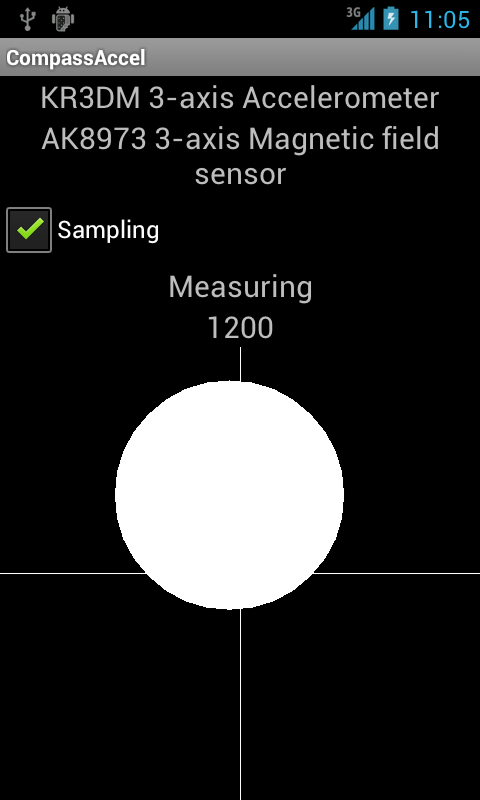
After the calibration you see the familiar ball that visualizes the measured motion acceleration (the size of the ball is proportional with the z component of the motion acceleration). As with the gyroscope case, the motion acceleration is rotated into the Earth's coordinate system. If you need the motion acceleration in the device's coordinate system, just remove the rotateToEarth() method invocation.

If you set DEBUG to true in SamplingService.java, the program creates a (potentially large) file containing measurement data as /sdcard/capture.csv. You can analyze it with this Sage script.

Now we have two methods of extracting motion acceleration. The gyroscope is more convenient because it is not subject to external magnetic fields or metal objects but is available in less devices. There are more hassles with the compass but at the end it works nicely too. The next step is to recognize movement patterns in the 3D motion acceleration vectors.

Saturday, March 3, 2012

PHONE_STATE broadcast and 4.0.3

Anybody out there who has experience with android.intent.action.PHONE_STATE broadcasts and 4.0.3? I wrote this simple application that is just a receiver for this broadcast intent. It works beautifully on 2.2 but does not capture any broadcasts on a Nexus S with the official Google 4.0.3 firmware. The manifest has the permission (XML mangling because of the blog engine):

    [uses-permission android:name="android.permission.READ_PHONE_STATE"/]

and the receiver:

       [receiver android:name=".PhoneIntentReceiver"
            android:enabled="true"
            android:exported="true"]
            [intent-filter]
                [action android:name="android.intent.action.PHONE_STATE" /]
            [/intent-filter]
        [/receiver]

Is this a 4.0.3 bug?

Thursday, March 1, 2012

Compensating accelerometer with the compass - the limitations

In the previous parts of our sensor processing series, we have seen how to use the gyroscope to separate the motion and the gravity acceleration components measured by the accelerometer. But gyroscope-equipped phones are rare. Can we have a "poor man's gyroscope" that is more widely deployed in today's devices?

Let's reiterate the problem. We have an accelerometer that is exposed to two main kinds of accelerations: gravity and motion acceleration. Gravity acceleration is always present. Sadly, its direction is not constant but changes with the direction of the device. If the device is subject to motion acceleration (e.g. the user is walking), motion acceleration is added to the gravity component. Motion acceleration vector changes dynamically due to the movement phases. If we have to assume that motion acceleration is present but we don't know the gravity acceleration vector, separating the gravity and motion acceleration components is impossible. We need another sensor therefore and we made a good use of the gyroscope so far.

The other evident sensor that can be used to determine the Earth's coordinate system relative to the device coordinate system is the compass or magnetic sensor. Compass is attractive because it is widely available in today's devices. Unfortunately it has certain drawbacks that make it more inconvenient to support the accelerometer than gyroscope. In this part I will go through the characteristics of the compass to set the expectations before we start to discuss, how to use it together with the accelerometer.

First the basics. The compass measures the magnetic field the device is exposed to. This magnetic field has many components. We are most interested in the Earth's magnetic field but obviously there are other disturbances, e.g. metal objects, magnets, magnetic fields generated by electric devices. The Earth's magnetic field is not trivial either. Contrary to a belief I hear often, the Earth's magnetic field points mostly downward, toward the center of the Earth. The effect is called magnetic inclination and it means that the Earth's magnetic field has a varying degree relative to the Earth's surface. Where I live, the inclination is  about 70 degrees. The component that compasses measure to find the "North" (more exactly: magnetic North) is just the x and y components of the magnetic field which are smaller than the z component.

External magnetic fields can make measuring the Earth's magnetic field virtually impossible. The graph below shows an extreme case when I started compass sampling and walked into an underground train that eventually left the station.
The x axis is the sample count (proportional to time), the y axis is the length of the magnetic field vector measured by the compass. You can see that around 1900 sample count the metal body of the train starts to show its effect. Then around 2400 the electrical traction motors of the train start to operate which generates at its peak 6 times larger magnetic field than the Earth's magnetic field. This magnetic field also varies in time as the power of the motors fall after the train is accelerated to its cruising speed. First rule therefore is to avoid large electric devices, particularly those that vary their power in time.

The compass also has characteristics that make life harder. The two diagrams below show two measurements. In each measurement the device was rotated around its y axis a full circle (see the SensorEvent documentation about device axes in Android) then it was rotated 90 degrees around its x axis and rotated fully around the y axis again. The two measurements were different only in their location. Both were performed in average rooms, relatively far from metal objects (as much as it is possible in average rooms and buildings).
We expect to see neat circles centered around the origo. What we see is that the circles are not centered around the origo but have characteristic offsets. Worse, those offsets are not the same even though the measurements were done with exactly the same device.


 In order to support the accelerometer with the compass, we have to swallow the following two limitations.
  • No magnetic fields around that vary in time (typically electric devices, trains, etc.)
  • The compass has to be calibrated at each location (by rotating the device around). This pretty much excludes measurements on the move (e.g. walking).
If these limitations are acceptable, however, then we have a reference sensor that can replace the accelerometer while the device is subject to motion acceleration and we can extract motion acceleration. We can implement those Wii-like games even if there is no gyroscope in the phone.

I tell you how in the next part.

Friday, February 10, 2012

Example application for accelerometer/gyroscope processing on Android

In the previous parts we have seen how to simulate the gravity vector with the gyroscope if the accelerometer is not able to measure gravity correctly (because it is subject to motion acceleration too beside the gravity acceleration) and how to update this simulated gravity vector from the accelerometer to prevent the accumulation of measurement errors. At the end of the previous post we had a gravity vector which was normally taken from the accelerometer but our algorithm switched to gyroscope simulation automatically when needed.

We need just one more step to enable cool applications and that step is very evident. If you remember my Droidcon 2011 presentation (slide 24), the acceleration measured by the accelerometer is the sum of gravity and motion acceleration. If both are present, they cannot be separated in the general case without additional sensor input. But now we have the gravity acceleration which is reasonably exact even if the accelerometer is subject to motion acceleration too. This means that we can extract the motion acceleration by subtracting the simulated gravity acceleration from the acceleration measured by the accelerometer.

This opens the way for applications based on dynamic movements much like the Wii games with Motion Plus accessory (which actually do the same as the Motion Plus accessory is really just a 2+1 axis gyroscope).

The example program can be downloaded from here.

After all these simulation script, let's see something hands-on. The example program is the implementation of all these ideas we have seen so far. You need an Android phone with gyroscope to test it. The gyroscope processing algorithm is implemented in SamplingService.java. GyroAccelActivity is really doing only visualization, getting callbacks from SamplingService.

When started, the service enters the calibration state. This state is necessary to get a good fix of the initial gravity vector so the device should not be moved when calibrating. The initial gyroscope drift experienced on my Nexus S also ceases during the calibration period.

Then the service enters the measuring state and implements everything we discussed so far. It samples the accelerometer and the gyroscope paralelly, simulates the gravity vector if it finds out that the accelerometer is probably subject to motion acceleration and calls back the activity with the calculated motion acceleration vector. The acceleration is shown as movement of a large white ball (quite ugly, actually). The x and the y components of the motion acceleration move the ball horizontally and vertically while the size of the ball is calculated from the z component of the motion acceleration.

Note that the motion acceleration is expressed in the coordinate system of the device itself, so you may get some unexpected result if the device is not parallel to the floor surface. As we have the gravity vector, rotating the motion acceleration vector to the Earth's coordinate system is simple exercise (took me several days to get it right ;-)). We calculate two rotations (around z and y axes) to rotate the gravity vector into the z axis. At the same time we rotate the motion acceleration vector with the same rotations. This yields a normalized motion acceleration vector that would have been measured if the device were parallel to the surface.

If you are done with playing the ball, you will notice that analyzing these 3D acceleration vectors are not trivial. You can try setting the SamplingService.DEBUG field to true, then the application produces the usual /sdcard/capture.csv file (beware, it can be large) that you can download to your computer and visualize with this Sage script.