The truth is that the low-voltage LED strip I used in
the previous post was a backup solution. Originally I bought a
230V-operated Christmas light with two independent LED strips but
adapting that beast to Bluetooth Low Energy turned out to be a bit
more problematic than I expected. I had to learn a bit about power
electronics first.
My LED light I used as a base in this post is a standard-issue Chinese-made device. Below you can see how it looks like, its original controller already stripped of its plastic protective housing.

The circuit is very similar to this one, except that mine had only two LED strips, instead of 4. In my version the controller chip had HN-803 marking and the strip-controlling thyristors are of type PCR 406. The modes the original controller supported were all zero-crossing ones so I retained this operation.
Very shortly about the zero-crossing vs. phase-angle mode of controlling thyristors or triacs. A good introduction can be found here. The thyristor is fed with a current that has frequent zero-crossings. This is necessary because once the thyristor is switched on, the simplest way to turn it off is to remove the current on the load. That is why the Graetz-bridge converting the 230V alternating current into direct current does not have the usual filtering capacitors. This guarantees that the current feeding the LED strips/thyristors has zero-crossings with 100 Hz frequency. After the zero-crossing the thyristor can be switched on again by just a mA-range current applied on its gate electrode. The phase difference between the zero-crossing and the moment the gate current is applied determines whether we use dimming or not. Then the thyristor will remain switched on until the next zero-crossing. As the frequency of these zero-crossings is just 100 Hz, pulse-width modulation we used in the previous post for dimming cannot be used, the human eye would notice the flickering with such a low PWM frequency. So the simple circuit I am going to present here can only be used to flash the LED strips but not for dimming them. Implementing phase angle-based dimming would not be too hard with the features of our microcontroller but I did not want to get into that in this post.
Warning: part of the circuits described in this post use high-voltage 230 V current. Do not try to build them if you do not have experience with high-voltage electronics because you risk electrocuting!
Our exercise looks very simple. We need to remove the HN-803 controller circuit, replace it with our nRF51822 BLE SoC and use 2 of the output pins of the SoC to turn on the thyristors. Once the SoC drives the output pin to low, the thyristor will switch off at the next zero-crossing which allows us to flash the LED strips with frequencies lower than 100 Hz. Unfortunately nothing is simple if high-voltage current is involved because this simple circuit would connect the ground of the microcontroller board to a wire with high-voltage current (HVGND on the schematic) risking electric shock if someone touches the microcontroller board or ground-connected metal parts (like connectors) when the circuit is in operation. So I built an optocoupler-based isolator pictured below (click to enlarge).

The isolator ensures that the microcontroller-side has nothing to do with high-voltage current so no special precautions need to be done when handling the MCU board. The isolator itself, along with the remaining parts of the original controller circuit (D1-D4, T1/T2 and of course, LED1 and LED2 representing the two LED strips) are placed in a separate enclosure box. R3 dissipates around 1W so make sure that the resistor in question can withstand this power, I used a 2W resistor.
Driving the low-voltage side of the optocoupler still requires about 5 mA so I introduced additional FETs on the SoC side to provide this current. The updated circuit looks like below (click to enlarge). This circuit can control one low-voltage LED strip (with dimming) and two high-voltage strips (with no dimming) at the same time.

In my implementation the isolator and the MCU boards are located in two enclosure boxes which allows modular deployment - if there are no high-voltage strips then the isolator box is not needed. The connection between the MCU and the isolator boxes are 4 mA current loops which is quite resistant to noise. So the connecting cable could be much longer than in the image below.

Now on to the software.
Click here to download the nRF51822 code.
Click here to download the Android code.
Compilation instructions can be found in the previous post. One warning: if you built the previous version and uploaded into the SoC, make sure that you mass-erase the chip (mass-erase.sh script provided in the download bundle) and upload everything again (soft device and updated application) because the BLE service description has changed and the nRF51822 SDK writes data into the flash about the service characteristics.
Again I propose that before you start to experiment with the Android application, test the BLE device with a BLE debug tool like the nRF Connect for Mobile. You will see that the high-voltage LED strips are controlled by a new BLE characteristic (the old one controlling the low-voltage strip is still available unchanged).
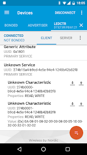
The byte array written into this characteristic is a blob that describes the light effect. The blob has two identical sections, each of them 9 bytes long. One section starts with 1 byte for the repetition counter then 4 times 2 bytes, each 2 byte subsection having 1 byte for the time duration (in 0.1 sec units) and one byte for the bit mask of the LED strips (bit 0->1 if LED strip #1 is to be on, bit 1->1 if LED strip #2 is to be on).
Regarding the Android application, there are no too many surprises. I used the now deprecated TabActivity because I did not feel like playing around with fragments for this simple prototype. The screen has separate tabs for the low- and the high-voltage strips like this:

The disconnection deficiency described in the previous post is still there. Make sure that you disconnect from the device after each manipulation (by pressing the Back button) because neither the device nor the Android application implements disconnection timeout so if you stay connected, nobody else will be able to connect to the LED strip controller. Otherwise have fun with these BLE-enabled Christmas lights!
My LED light I used as a base in this post is a standard-issue Chinese-made device. Below you can see how it looks like, its original controller already stripped of its plastic protective housing.

The circuit is very similar to this one, except that mine had only two LED strips, instead of 4. In my version the controller chip had HN-803 marking and the strip-controlling thyristors are of type PCR 406. The modes the original controller supported were all zero-crossing ones so I retained this operation.
Very shortly about the zero-crossing vs. phase-angle mode of controlling thyristors or triacs. A good introduction can be found here. The thyristor is fed with a current that has frequent zero-crossings. This is necessary because once the thyristor is switched on, the simplest way to turn it off is to remove the current on the load. That is why the Graetz-bridge converting the 230V alternating current into direct current does not have the usual filtering capacitors. This guarantees that the current feeding the LED strips/thyristors has zero-crossings with 100 Hz frequency. After the zero-crossing the thyristor can be switched on again by just a mA-range current applied on its gate electrode. The phase difference between the zero-crossing and the moment the gate current is applied determines whether we use dimming or not. Then the thyristor will remain switched on until the next zero-crossing. As the frequency of these zero-crossings is just 100 Hz, pulse-width modulation we used in the previous post for dimming cannot be used, the human eye would notice the flickering with such a low PWM frequency. So the simple circuit I am going to present here can only be used to flash the LED strips but not for dimming them. Implementing phase angle-based dimming would not be too hard with the features of our microcontroller but I did not want to get into that in this post.
Warning: part of the circuits described in this post use high-voltage 230 V current. Do not try to build them if you do not have experience with high-voltage electronics because you risk electrocuting!
Our exercise looks very simple. We need to remove the HN-803 controller circuit, replace it with our nRF51822 BLE SoC and use 2 of the output pins of the SoC to turn on the thyristors. Once the SoC drives the output pin to low, the thyristor will switch off at the next zero-crossing which allows us to flash the LED strips with frequencies lower than 100 Hz. Unfortunately nothing is simple if high-voltage current is involved because this simple circuit would connect the ground of the microcontroller board to a wire with high-voltage current (HVGND on the schematic) risking electric shock if someone touches the microcontroller board or ground-connected metal parts (like connectors) when the circuit is in operation. So I built an optocoupler-based isolator pictured below (click to enlarge).

The isolator ensures that the microcontroller-side has nothing to do with high-voltage current so no special precautions need to be done when handling the MCU board. The isolator itself, along with the remaining parts of the original controller circuit (D1-D4, T1/T2 and of course, LED1 and LED2 representing the two LED strips) are placed in a separate enclosure box. R3 dissipates around 1W so make sure that the resistor in question can withstand this power, I used a 2W resistor.
Driving the low-voltage side of the optocoupler still requires about 5 mA so I introduced additional FETs on the SoC side to provide this current. The updated circuit looks like below (click to enlarge). This circuit can control one low-voltage LED strip (with dimming) and two high-voltage strips (with no dimming) at the same time.

In my implementation the isolator and the MCU boards are located in two enclosure boxes which allows modular deployment - if there are no high-voltage strips then the isolator box is not needed. The connection between the MCU and the isolator boxes are 4 mA current loops which is quite resistant to noise. So the connecting cable could be much longer than in the image below.

Now on to the software.
Click here to download the nRF51822 code.
Click here to download the Android code.
Compilation instructions can be found in the previous post. One warning: if you built the previous version and uploaded into the SoC, make sure that you mass-erase the chip (mass-erase.sh script provided in the download bundle) and upload everything again (soft device and updated application) because the BLE service description has changed and the nRF51822 SDK writes data into the flash about the service characteristics.
Again I propose that before you start to experiment with the Android application, test the BLE device with a BLE debug tool like the nRF Connect for Mobile. You will see that the high-voltage LED strips are controlled by a new BLE characteristic (the old one controlling the low-voltage strip is still available unchanged).

The byte array written into this characteristic is a blob that describes the light effect. The blob has two identical sections, each of them 9 bytes long. One section starts with 1 byte for the repetition counter then 4 times 2 bytes, each 2 byte subsection having 1 byte for the time duration (in 0.1 sec units) and one byte for the bit mask of the LED strips (bit 0->1 if LED strip #1 is to be on, bit 1->1 if LED strip #2 is to be on).
Regarding the Android application, there are no too many surprises. I used the now deprecated TabActivity because I did not feel like playing around with fragments for this simple prototype. The screen has separate tabs for the low- and the high-voltage strips like this:

The disconnection deficiency described in the previous post is still there. Make sure that you disconnect from the device after each manipulation (by pressing the Back button) because neither the device nor the Android application implements disconnection timeout so if you stay connected, nobody else will be able to connect to the LED strip controller. Otherwise have fun with these BLE-enabled Christmas lights!


